The ATtiny85 is a great little chip, but decidedly lacking when it comes to IO pins. While excellent mobile robots can certainly be built around its innate capabilities, I decided that I needed to expand beyond 5 pins for the sorts of applications I had in mind. Figuring out different ways to do so has proven wonderfully educational.
The obvious and easiest place to start was with shift registers, as first suggested to me by the Sparkfun Tiny AVR Programmer Hookup Guide.
Accordingly, I acquired some 74HC165 (PISO: Parallel-In/Serial-Out) and 74HC595 (SIPO: Serial-In/Parallel-Out) shift register chips, and set about learning how to make the Tiny talk to one, the other, and then both of them.
There are a plethora of helpful guides on using these chips with Arduino:
- http://www.ecs.umass.edu/ece/m5/tutorials/parallel_serial_shift_register.html
- http://playground.arduino.cc/Code/ShiftRegSN74HC165N
- https://learn.sparkfun.com/tutorials/shift-registers
- https://learn.adafruit.com/adafruit-arduino-lesson-4-eight-leds/the-74hc595-shift-register
- http://www.electronics-tutorials.ws/sequential/seq_5.html
- http://www.arduino.cc/en/Tutorial/ShiftOut
These methods (with the exception of those utilizing the shiftIn() function) transfer easily to the ATtiny85. However, because it lacks sufficient IO pins and built-in SPI support, talking to more than one (non-daisy-chained) shift register at once is not so easy on the smaller chip.
The solution I found was to share a single clock line between the PISO and SIPO shift registers, with separate latch and data lines for each, holding the various enables and inhibits steady. While this approach has drawbacks, such as requiring firm temporal separation of input and output phases and the need to refresh the SIPO register for each output, it allowed me to easily control the two shift registers with only 5 pins.
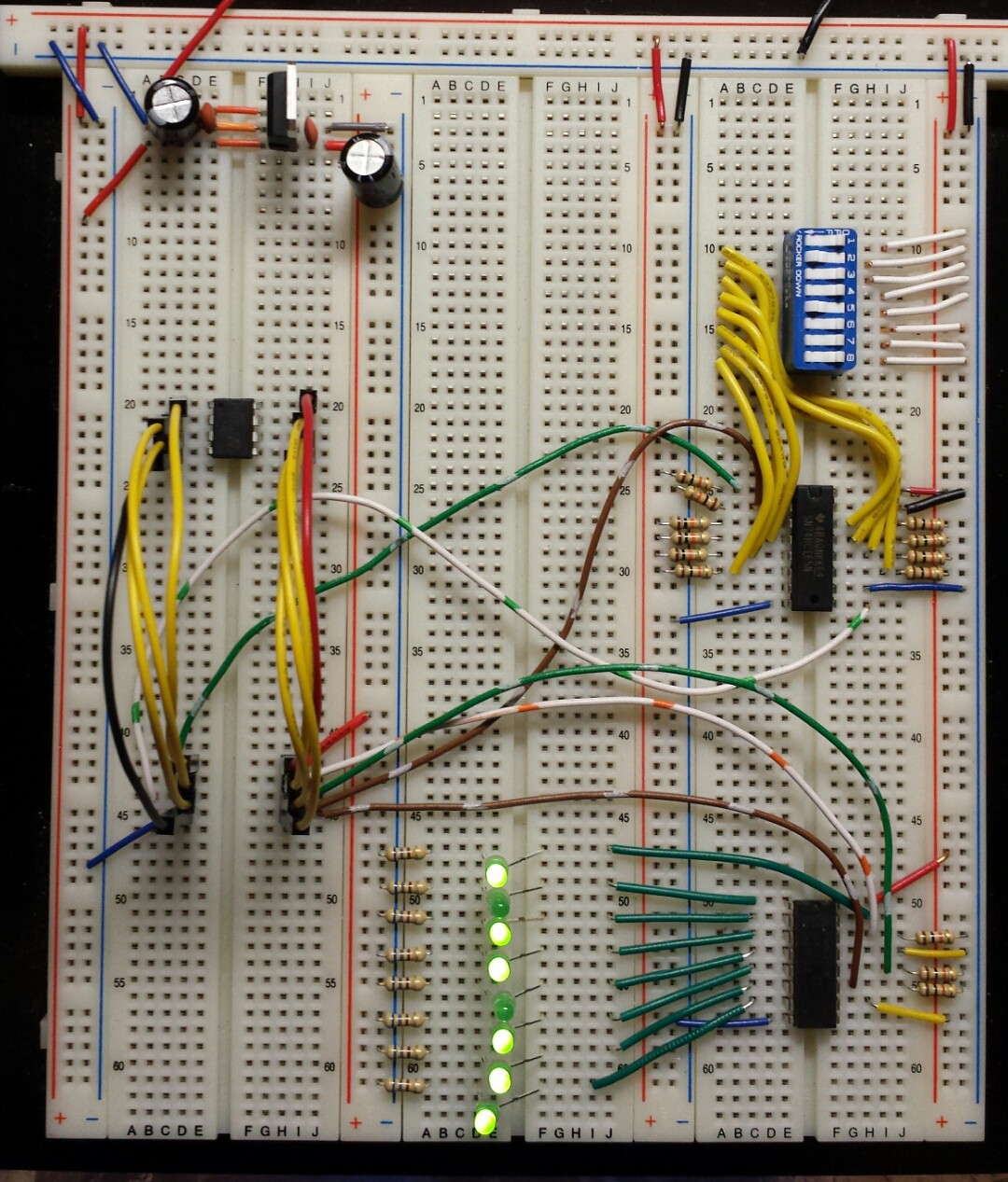
As a first project, I chose to reproduce the setup demonstrated in Sparkfun's introductory Shift Register video, reading the state of an 8-position DIP switch with a 74HC165 and turning on a corresponding bank of 8 LEDs through a 74HC595.
Here's a photo of the setup (schematic forthcoming soon!):
And here's the code:
// 8xDIP --> 74HC165 --> ATtiny85 --> 74HC595 --> 8xLED
// ====================================================================================
// Updated 05May2015
// By C. Parkin


// Pins
int clockPin    = 0;    // *COMMON* connected to pin 11 (SH_CP, SRCLK) of 595, pin 2 (CLK/CP) of 165
int outLatchPin    = 1;    //connected to pin 12 (ST_CP, RCLK) of 595
int outDataPin    = 2;    //connected to pin 14 (DS, SER) of 595
int inLatchPin    = 3;    //connected to pin 1 (SH/LD, PL)("shift/load") of 165
int inDataPin    = 4;     //connected to pin 9 (QH, Q7) ("data") of 165

// Other Pin Settings:
// 165:
//     Pin 15 (CLK INH or CE) ("clock enable") to GROUND (active low)
//      Pin 10 (SER, DS) ("serial data input") to GROUND (when not connected to another 165)
//     Pin 11-14 (A-D), 3-6 (E-H) to parallel inputs
//    Pin 16 to Vcc
//    Pin 8 to GND
//    Pin 7 (Q_H or Q_7) ("complementary output from the last stage") left unconnected?(as shown on 2+ sources)
//
// 595:
//    Pin 10 (MR, SRCLR) ("Master Reset", "Serial Clear") to Vcc
//    Pin 13 (OE) ("output enable input") to GROUND (active LOW)
//    Pin 16 to Vcc
//    Pin 8 to GND
//    Pin 15, 1-7 to parallel outputs
//      Pin 9 (Q7") ("Serial out") left unconnected w/only 1 chip?


// Serial storage variables
byte inByte;    //for the 8 values loaded FROM the 165 shift register
byte outByte;    //for the 8 values loaded TO the 595 shift register


// function to read in from 165

void getter()
{

    // take the latch pin low to move the parallel inputs into the shift register
    digitalWrite(inLatchPin, LOW);
    delayMicroseconds(5);   //some resources suggest 10 for this; try that if 5 doesn't work.
    digitalWrite(inLatchPin, HIGH);

    // populate the inByte
    for (int bitCount = 0; bitCount < 8; bitCount++)
    {
        // set the current bit to the current value of inDataPin
        bitWrite(inByte, bitCount, digitalRead(inDataPin));

        //pulse the clock to shift to the next serial-in bit
        digitalWrite(clockPin, HIGH);
        delayMicroseconds(5);
        digitalWrite(clockPin, LOW);
    }

}


// function to write out to 595

void putter()
{

    // output the outByte

    for (int bitCount = 0; bitCount < 8; bitCount++)
    {
        // set outDataPin according to current bit value:
        digitalWrite(outDataPin, bitRead(outByte, bitCount));

        //pulse the clock
        digitalWrite(clockPin, HIGH);
        delayMicroseconds(5);
        digitalWrite(clockPin, LOW);
    }

    //take the latch pin high to move the new sequence to the parallel output
    digitalWrite(outLatchPin, HIGH);
    delayMicroseconds(5);
    digitalWrite(outLatchPin, LOW);

}


void setup()
{

    // Common Clock Pin
    pinMode(clockPin, OUTPUT);    //sends pulses to the shift registers


    // IN specific pins
    pinMode(inLatchPin, OUTPUT);     //latch/loads the current parallel in values into the shift register for serial output to tiny
    pinMode(inDataPin, INPUT);    //serial input from shift register to tiny


    // OUT specific pins
    pinMode(outLatchPin, OUTPUT);    //shifts current serial values in register to register outputs
    pinMode(outDataPin, OUTPUT);    //serial output from tiny to shift register


    // Set pins to proper states: (Is this better done in the loop or getter/putter functions?)
    digitalWrite(inLatchPin, HIGH); // SH/LD is active low, so we set it high to avoid premature loading
    digitalWrite(clockPin, LOW);    // clock is low-to-high edge-triggered, so start low
    digitalWrite(outLatchPin, LOW); // SH_CP is positive-edge triggered, so start low

    // Initialize in/outBytes to zero
    inByte = B00000000;
    outByte = B00000000;

}


void loop()
{

    getter();

    // Here is where we would, in a more complicated program, figure out what to do with the input data
    outByte = inByte;    // In this simple case, simply pass it over to the Putter function

    putter();

}
Worked like a charm!
Up next: adapting this setup (PATS: PISO --> ATtiny85 --> SIPO) to read bump switches and control motors for a simple mobile robot.
Discussions
Become a Hackaday.io Member
Create an account to leave a comment. Already have an account? Log In.