In addition to a handful of TV-B-Gone kits, the feeding frenzy at Radioshack also yielded a dozen SeeedStudio Motor Shield V2.0 boards for a few bucks a piece. They aren't ordinarily the easiest, cheapest, or anything close to the best way of driving motors, but I had them already, so it seemed like the avenue to explore for the next phase of this project.
What I discovered, upon investigating their usage, is that these motor shields seems to be pieces of junk compared to the others on the market. The documentation available is especially poor, and in hours of scouring the web, I could find very, very few instances of anyone successfully using the buggers.
However, based on cryptic, incomplete official documentation and what few implementation examples I could find, it seemed to me that they should, in principle, be simple to use, even without getting my Arduino out of the box.
Happily, after a protracted struggle, I found this to be true.
Here are the pins of importance:
Pin 8: Motor A Control Line 1 (IN1)
Pin 11: Motor A Control Line 2 (IN2)
Pin 9: Motor A Speed Control (EA)
Pin 12: Motor B Control Line 1 (IN3)
Pin 13: Motor B Control Line 2 (IN4)
Pin 10: Motor B Speed Control (EB)
The few examples all show the control line as taking a PWM signal, but looking at the data sheet for the L298 IC (Dual Full-Bridge Driver) which drives the thing, the control line simply appears to be an enable. In any case, a constant 5V signal should equate to a 100% duty cycle PWM signal, so one can enable the motor with a simple logical HIGH (which is important as I'm using a shift register to drive the thing).
Very simply (as derived from the "official" Github example), for each motor:
| Enable (EN) | Input1 (IN1) | Input2 (IN2) | Function |
| H | L | H | Turn CC |
| H | H | L | Turn CCW |
| H | L | L | Fast Stop |
| H | H | H | Fast Stop |
| L | X | X | Fast Stop |
I managed (with help from an EE of my acquaintance) to wire up a simple set of switches to confirm the control patterns before risking any chips, then set about connecting it to the PISO Shift Register --> ATtiny85 --> SIPO Shift Register (P.A.T.S.) circuitry described in the last project log.
The "behavior" pattern that I wanted the first version of the One-Tiny Bot to exhibit is simple: proceed forward, with two "whisker" switches to the front left and right. If the left switch is pressed, stop, back up, turn right, and proceed. If the right switch is pressed, stop, back up, turn left, and proceed. If both are pressed, stop, back up, turn around, and proceed.
Extending the program for illuminating LEDs based on DIP switch input to controlling motors was relatively straightforward. Remembering that the bit order (from least-significant) is opposite of the shift register D/Q pin order, this pattern corresponds to the following bytes:
FORWARD: 101101XX
STOP: 000000XX
REVERSE: 110110XX
RIGHT: 101110XX
LEFT: 110101XX
Where the last two bits are not used in motor control.
Rathering to add functionality rather than remove it, I left the DIP switch in place, and tied in two pull-down pushbuttons to 74HC165 pins 11 (right button) and 12 (left button). Ignoring all other inputs but the last, which I used as an on/off switch, the input byte encoding is:
(left button)-(right button)-X-X-X-X-X-(ON/OFF)
A handful of elseif's, and the thing worked like a charm.
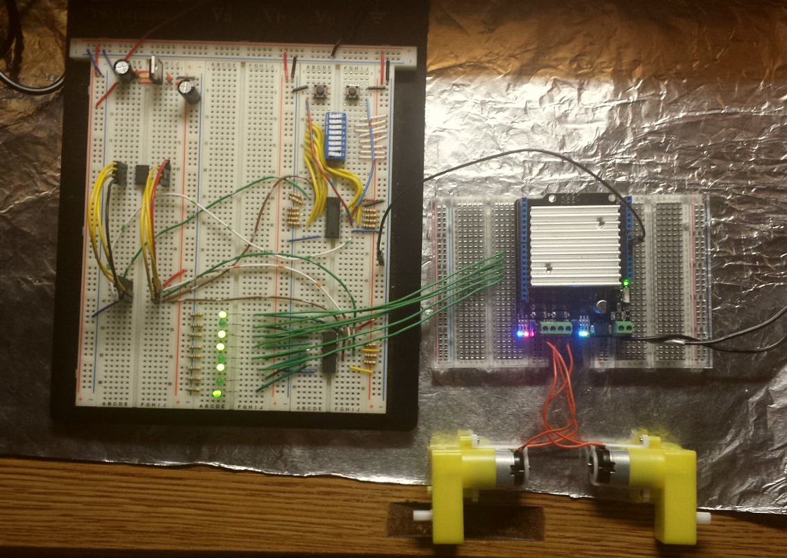
An essential thing to note is that *the control circuitry and the motor shield must have a common ground* in order to avoid a ground potential error in the signaling.
Here is a poor quality photograph of the setup. Schematic forthcoming, I swear!
And here's the annotated code:
// 8xDIP/PUSHBUTTONS --> P.A.T.S. --> SeeedMotorShield/8xLED --> 2 Motors
// ===========================================================================================
// Updated 13May2015
// By C. Parkin


// Pins
int clockPin    = 0;    // *COMMON* connected to pin 11 (SH_CP, SRCLK) of 595, pin 2 (CLK/CP) of 165
int outLatchPin    = 1;    //connected to pin 12 (ST_CP, RCLK) of 595
int outDataPin    = 2;    //connected to pin 14 (DS, SER) of 595
int inLatchPin    = 3;    //connected to pin 1 (SH/LD, PL)("shift/load") of 165
int inDataPin    = 4;     //connected to pin 9 (QH, Q7) ("data") of 165

// Other Pin Settings:
// 165:
//     Pin 15 (CLK INH or CE) ("clock enable") to GROUND (active low)
//      Pin 10 (SER, DS) ("serial data input") to GROUND (when not connected to another 165)
//     Pin 11-14 (A-D), 3-6 (E-H) to parallel inputs
//    Pin 16 to Vcc
//    Pin 8 to GND
//    Pin 7 (Q_H or Q_7) ("complementary output from the last stage") left unconnected (unless inverted output desired)
//
// 595:
//    Pin 10 (MR, SRCLR) ("Master Reset", "Serial Clear") to Vcc
//    Pin 13 (OE) ("output enable input") to GROUND (active LOW)
//    Pin 16 to Vcc
//    Pin 8 to GND
//    Pin 15, 1-7 to parallel outputs
//      Pin 9 (Q7") ("Serial out") left unconnected w/only 1 chip


// Serial storage variables
byte inByte;    //for the 8 values loaded FROM the 165 shift register
byte outByte;    //for the 8 values loaded TO the 595 shift register


// function to read in from 165

void getter()
{

    // take the latch pin low to move the parallel inputs into the shift register
    digitalWrite(inLatchPin, LOW);
    delayMicroseconds(5);   //some resources suggest 10 for this; try that if 5 doesn't work.
    digitalWrite(inLatchPin, HIGH);


    // populate the inByte
    for (int bitCount = 0; bitCount < 8; bitCount++)
    {
        // set the current bit to the current value of inDataPin
        bitWrite(inByte, bitCount, digitalRead(inDataPin));

        //pulse the clock to shift to the next serial-in bit
        digitalWrite(clockPin, HIGH);
        delayMicroseconds(5);
        digitalWrite(clockPin, LOW);
    }

}


// function to write out to 595

void putter()
{

    // output the outByte
    for (int bitCount = 0; bitCount < 8; bitCount++)
    {
        // set outDataPin according to current bit value:
        digitalWrite(outDataPin, bitRead(outByte, bitCount));

        //pulse the clock
        digitalWrite(clockPin, HIGH);
        delayMicroseconds(5);
        digitalWrite(clockPin, LOW);
    }


    //take the latch pin high to move the new sequence to the parallel output
    digitalWrite(outLatchPin, HIGH);
    delayMicroseconds(5);
    digitalWrite(outLatchPin, LOW);

}


// function to stop all motion: STOP(B00000000)
void fullStop()
{

    outByte = B00000010;
    putter();

}


// function to drive forward (both motors CW): FORWARD(B10110100)
void forward()
{

    outByte = B10110101;
    putter();
    delay(250); //indirectly sets turn angle... Tweek this!

}


// function to drive backwards (both motors CCW): REVERSE(B11011000)
void reverse()
{

    outByte = B11011001;
    putter();
    delay(250); //indirectly sets turn angle... Tweek this!

}


// function to turn right (left motor CW, right motor CCW): RIGHT(B10111000)
void right()
{

    outByte = B10111001;
    putter();
    delay(250); //indirectly sets turn angle... Tweek this!

}


// function to turn left (left motor CCW, right motor CW): LEFT(B11010100)
void left()
{

    outByte = B11010101;
    putter();
    delay(250); //indirectly sets turn angle... Tweek this!

}


//function to turn around (same as right turn, but with longer delay)
void turnAround()
{

    outByte = B10111001;
    putter();
    delay(500); //indirectly sets turn angle... Tweek this!

}


void setup()
{

    // Common Clock Pin
    pinMode(clockPin, OUTPUT);    //sends pulses to the shift registers


    // IN specific pins
    pinMode(inLatchPin, OUTPUT);     //latch/loads the current parallel in values into the shift register for serial output to tiny
    pinMode(inDataPin, INPUT);    //serial input from shift register to tiny


    // OUT specific pins
    pinMode(outLatchPin, OUTPUT);    //shifts current serial values in register to register outputs
    pinMode(outDataPin, OUTPUT);    //serial output from tiny to shift register


    // Set pins to proper states: (Is this better done in the loop or getter/putter functions?)
    digitalWrite(inLatchPin, HIGH); // SH/LD is active low, so we set it high to avoid premature loading
    digitalWrite(clockPin, LOW);    // clock is low-to-high edge-triggered, so start low
    digitalWrite(outLatchPin, LOW); // SH_CP is positive-edge triggered, so start low


    // Initialize inByte to 255 (all inputs inactive) and outByte to 0 (all outputs inactive)
    inByte = B11111111;
    outByte = B00000000;

}


void loop()
{

    getter();


    // HERE is where we look at the inByte, decide what to output to the motors.

    // (Remember that Bit Number is the opposite of SR pin! eg D/Q0=B7, D/Q1=B6 ... D/Q7=B0)
    // Only need first six lines to control motor shield, so outByte will always be XXXXXX00
    // Attach Pull-down pushbuttons on 165 pins 11 (right button) and 12 (left button)

    // inByte bit encoding:  (left button)-(right button)-X-X-X-X-X-(ON/OFF)
    // outByte bit encoding: (EN1,2)-(IN1)-(IN2)-(EN3,4)-(IN3)-(IN4)-X-X

    // DIP8 is on/off. IF xxxxxxx0 = switched off; full STOP(B00000000), BREAK

    // With all 8DIP switches in the OFF position, a button press will pull the line low:
    // ============================================================================================
    // Case B11111111 = no button press: keep going FORWARD(B10110100), BREAK
    // Case B01111111 = left button pressed: STOP(B00000000), WAIT, REVERSE(B11011000), WAIT, RIGHT(B10111000), WAIT, FORWARD(B10110100), BREAK
    // Case B10111111 = right button pressed: STOP(B00000000), WAIT, REVERSE(B11011000), WAIT, LEFT(B11010100), WAIT, FORWARD(B10110100), BREAK
    // Case B00111111 = both buttons pressed: STOP(B00000000), WAIT, REVERSE(B11011000), WAIT, RIGHT(B10111000), WAIT-LONGER, FORWARD(B10110100), BREAK


    if ( bitRead(inByte,0) == 1 )
    {
        // if the on switch is off, stop everything
            fullStop();
    }
    else
    {
                if (bitRead(inByte,7)==0 && bitRead(inByte,6)==1)
                {
                  // left button press
                  fullStop();
             reverse();
           right();
          forward();
                }
                else if (bitRead(inByte,7)==1 && bitRead(inByte,6)==0)
                {
                  // right button press
          fullStop();
          reverse();
          left();
          forward();
                }
                else if (bitRead(inByte,7)==0 && bitRead(inByte,6)==0)
                {
                  // both buttons pressed
          fullStop();
          reverse();
          turnAround();
          forward();
                }
                else if (bitRead(inByte,7)==1 && bitRead(inByte,6)==1)
                {
              // no button presses
          forward();
                }
                else
                {
                    // stop the bot on strange input;
          fullStop(); // !!!
                }
        }
}
Up next: organization, miniaturization, mobilization, and mechanical mounting...
Discussions
Become a Hackaday.io Member
Create an account to leave a comment. Already have an account? Log In.