Well, I have not did very good about keeping a project log. Here is the (hopefully) final project.

Figure 1: The internet enabled smoke alarm on the benchtop
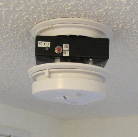
Figure 2: The internet enabled smoke alarm installed on the ceiling.
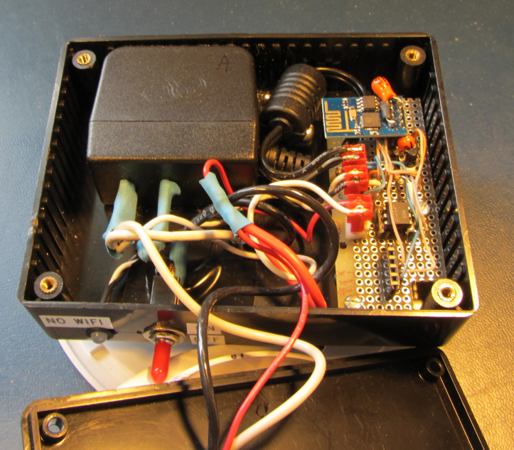
Figure 3: Inside of the Hammond enclosure
Oh, this is the misbehaving smoke alarms I mentioned in the project description.
When reverse engineering part of the commercial FireX smoke alarm schematic, I took digital images of the top and bottom side of the PCB. I then over layed the images in http://paint.net. Then, the opacity was adjusted to see both the traces on the bottom and the components on the top side. (This technique has been written about on various sites)
There are three wires going to each smoke alarm:
1) 120VAC
2) Common
3) Network
The 120VAC and common are incredibly fortunate. This makes it easy to power the ESP8266 module with a 120VAC to 3.3VDC wall pack adapter. The network line connects all 6 smoke alarms. Normally, the network line is at the same level as common. But, when the smoke alarms are sounding an alert, the network line rises about 9 volts above common. This causes all 6 smoke alarms to sound an alert. This network wire is connected to the ESP8266, through an optocoupler. The optocoupler has several advantages:
1) The optocoupler is high impedance, so it will not interfere with the smoke alarm operation.
2) The optocoupler electrically isolates the smoke alarm from the ESP8266.
3) The optocoupler is one directional. So, if some evil-hacker guy gets into the ESP8266, he could not set off the fire alarm. (I'm not 100% sure if the 3.3V logic line from the ESP8266 would set off the smoke alarm)
Now that it is known how the network line operates, here is a schematic of the smoke alarm modification.
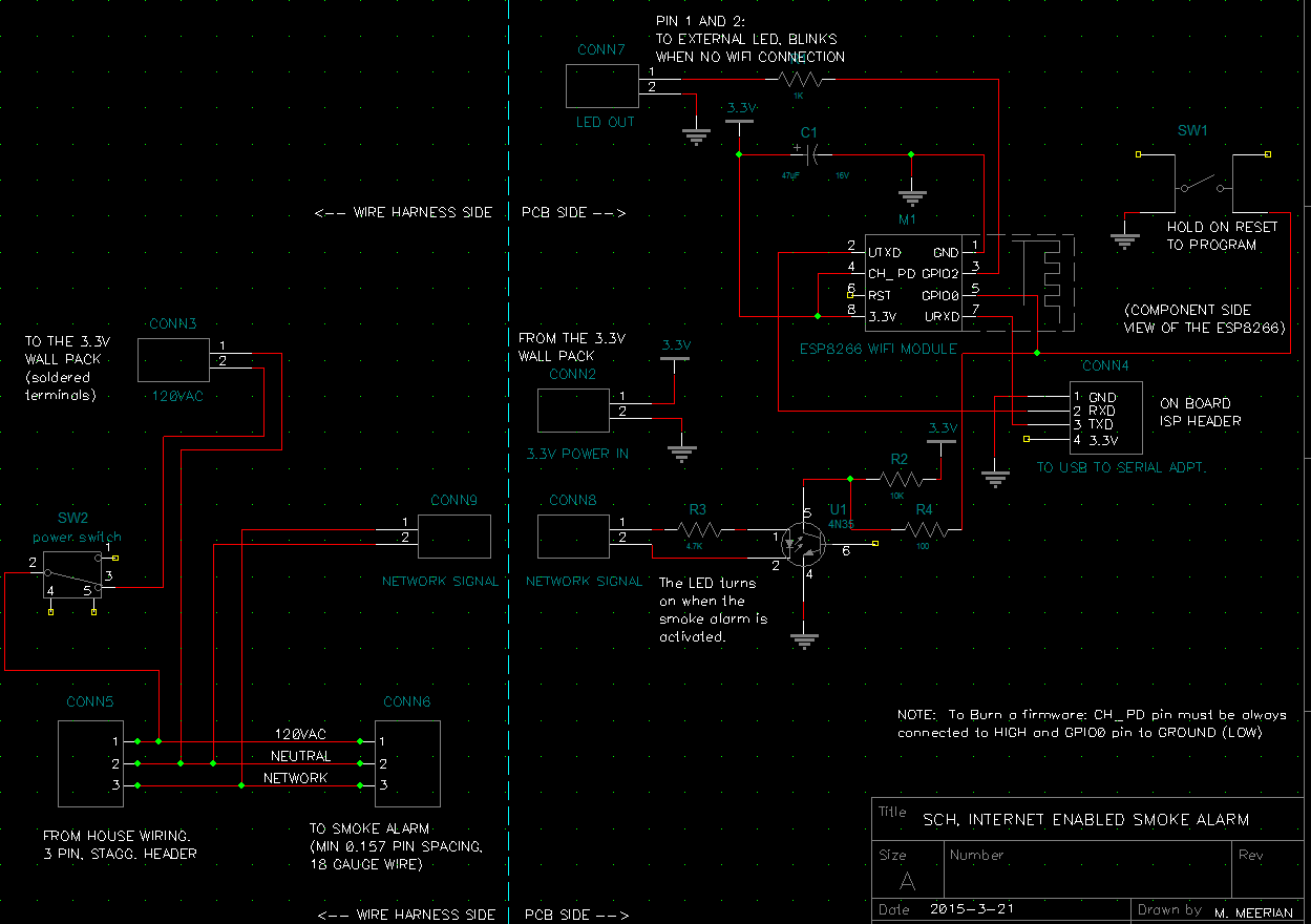
Figure 4: Schematic to add internet connectivity to a smoke alarm.
There really isn't too much to the hardware. When the network line goes to 9V above common, the optocoupler turns on. This changes the state of the I/O line going to the ESP8266. There is a two wire cable going to the white LED. The LED blinks when there the wireless router is not found. The 3.3V wall pack powers the ESP8266. The schematic has a few details noted on it.
The software I used for the ESP8266 module is written in Lua. The NodeMCU firmware was loaded in the module. The module is running version 20150318 of NodeMCU.
Here is the code:
-- 	Matt Meerian
-- 	Date:  5-16-2015
-- 	Origin:  This started as an example from the internet (there are several modified snippets)
--	Target:  ESP8266 module
--	Connection to target:  USB to 9600 baud, 3.3V
--	Downloader:  ESP8266 LuaLoader 0.83 or later
--	Firmware running on the ESP8266:  NodeMCU 0.9.5 build 20150318  powered by Lua 5.1.4
--	Description:  (NOTE:  This firmware should be the only file on the ESP8266 module when run)
--		This script will send an email to my yahoo account when the networked smoke alarms sound an alert.
--		There are 6 networked smoke alarms in the house:  Kiddie i4618.  I have reverse engineered
--		part of the schematic.  There are three wires going to the smoke alarm:  120VAC and a
--		"network" wire.  The network wire is normally at 0V.  When the alarm is going off, the network
--		line goes up to 9V.  This then sets off the other smoke alarms on the network.  I have
--		used an optocoupler to tap off of this network line and trigger the input of the ESP8266 module.
--	You need to connect to a wireless router (AP) before you run the "dofile":
-- 		wifi.setmode(wifi.STATION)
--		wifi.sta.config("NSA_mobile_surveillance","frn...")
--		You can then get your wifi by:  = wifi.sta.getip()
--	NOTE:  The email alert is sent by pushingbox.
--	When running a new lua script in LuaLoader:
--		Press the "Upload File" button.  (wait)
--		Press the "Restart" button.
--		Press the "dofile" button to run the script.
--	How to flash lua firmware into the ESP8266:
--		Use esp8266_flasher.exe			Follow the instructions there

led_output_pin=4	--This is the pin for the "wifi not connected" LED blink
opto_input_pin = 3	--The optocoupler input pin
debug_cntTick = 0
timer_between_emails=0
timer_minute=0	--This is used to count up to a minute
wifi_gone_alert=0
email_sent_timeout=0
const_min_time=30	--this is a "constant", if timer is at 2 seconds, then a value of 30 would be 1 min
const_email_series_delay=200	--if a series of emails has started, do not send anymore for an hour (if the timer is 2 seconds, then the value should be 1800)
host="http://api.pushingbox.com"	--This is the address to send an alert email
ipnr=0		--holds the IP address
CntTimer=1	--allows the code in the "send_pushingbox_email" routine to be run twice

gpio.mode(opto_input_pin,gpio.INPUT,gpio.PULLUP)	--make the optocoupler pin an input
gpio.mode(led_output_pin,gpio.OUTPUT)	--make the "no wifi" LED alert pin an output.
gpio.write(led_output_pin,gpio.LOW)

--This timer happens every four seconds
tmr.alarm(0, 4000, 1, function()
	--print("testing...")
	check_smoke_alarm()		--
	debug_cntTick=debug_cntTick+1		--counts the number of times through the timer
	print(debug_cntTick)
	if debug_cntTick > 50000 then	--reset the counter if the number is getting large
		debug_cntTick=1	--reset the value
	end
	check_wifi_status()		--blink an LED if there is no wifi signal
	timer_minute=timer_minute+1
	if timer_minute>const_min_time then	--This timer happens every minute.
		timer_minute=0	--reset the minute counter
	end
end )

--This function looks to see if there is a wifi signal.  If not, it blinks a red LED.
function check_wifi_status()
	if wifi.sta.getip()==nil then	--are we attached to a wireless router?
		print("no IP address")	--no wifi connection, start blinking an LED
		if wifi_gone_alert==0 then	--Since we do not have an internet connection, start blinking a red LED
			wifi_gone_alert=1	--next time through, turn off the red LED
			gpio.write(led_output_pin,gpio.HIGH)	--turn on the red LED, we will be blink'n
		else
			wifi_gone_alert=0	--next time through, turn on the red LED
			gpio.write(led_output_pin,gpio.LOW)		--turn off the red alert LED, we will be blink'n
		end
	else	--we do not need to blink the alert LED, so turn if off
		--print("we have an ip address")
		wifi_gone_alert=0	--we do not need any more red LED blinking
		gpio.write(led_output_pin,gpio.LOW)		--make sure the red LED is not on
	end
end

--This function looks at an input pin (through an opto coupler), to see if the smoke alarm is going off
--  If the alarm is going off, it sends an email
function check_smoke_alarm()
	if gpio.read(opto_input_pin)==1  then	--The smoke alarm is not going off
		--print("-no alarm-")	--this is run when the smoke alarm is off
		if email_sent_timeout==0 then	--only allow an email to be sent if an email has not been sent recently
			timer_between_emails=0	--The alarm is not sounding, so reset the email counter
		end
	else		--The smoke alarm is going off
		print("smoke alarm sounding!")	--this is run when the optocoupler sees 9V (alarm of on the smoke alarm is active)
		if timer_between_emails==0 then
			print("First email sent")
			send_pushingbox_email()
			email_sent_timeout=const_email_series_delay	--if we have sent an email recently, don't allow another series of emails to be sent out right away
		end
		if timer_between_emails==20 then	--is it time to send the second email?
			print("second email sent")
			send_pushingbox_email()
		end
		if timer_between_emails==40 then	--is it time to send the third email?  The house has probably burned down by now.  fuck.
			print("third email sent")
			send_pushingbox_email()
		end
		if timer_between_emails<100 then	--the smoke alarms must have been on for a long time!
			timer_between_emails=timer_between_emails+1		--counting up to the next email that can be sent out
		end
	end
	if email_sent_timeout>0 then	--if we have sent an email recently, don't allow another series of emails to be sent out right away
		email_sent_timeout=email_sent_timeout-1		--counting down to allow another series of emails to be sent out
	end
end

--This routine uses a "get" command to have the Pushingbox web site send an email.
--This code snippet was copied from the internet
function send_pushingbox_email()
	CntTimer=1	--we have to go through this routine twice in order for the email to be sent
	tmr.alarm(1, 4000,1, function()
		print("CntTimer: ")	--debug
		print(CntTimer)	--debug
		CntTimer=CntTimer+1
		if CntTimer>2 then	--allows the timer to only run through twice
			tmr.stop(1)	--stop the timer after two times through
		end
		sk=net.createConnection(net.TCP, 0)
		print("A")	--debug
		sk:dns(host,function(conn,ip)
			ipnr=ip
			print("B")	--debug
		end)
		conn=net.createConnection(net.TCP, 0)
		print("C")	--debug
		conn:on("receive", function(conn, payload) print(payload) end )
		print("D")	--debug
		conn:connect(80,ipnr)
		print("E")	--debug
		conn:send("GET /pushingbox?devid=vD60F1 HTTP/1.1\r\nHost: "..host.."\r\nConnection: keep-alive\r\nAccept: */*\r\n\r\n")  --use your own V
		print("F")	--debug
	end)
end
This is my first Lua program. I had to borrow heavily from forum examples in http://esp8266.com. There are a bunch of really talented people there.
There are a couple of things I would like to do in the future:
1) Recess all of the electronics into the ceiling. The Hammond enclosure hanging down from the ceiling is somewhat of an eye sore.
2) Create a web server on the ESP8266. It would be nice to hold debugging information in a web page. Then, when an email is not sent, I can look back at the history. It would also be nice to change the wifi access point and password remotely.
3) Make a custom circuit board for the ESP8266. I used perf-board with point to point wiring in the prototype. It would be more tidy to do a PCB layout and send out the gerbers for a professional board.
There is lots of room for improvement. Anyway, let me know if you have questions and I will try to get to them.