 sbi.gaijin
Okay, I cheated (just a little bit). Even before we built the house, we could see that this was going to be an issue, so when I was panelling the internal walls I left spaces for ducts to run from the lounge area, through the under-stairs storage area, to strategically placed openings in the walls of the "cold" rooms. The plan was to use forced air from the "warm" lounge area to provide warmth from the woodstove.
The Cheek of it:
Yes, I admit it ...I'm submitting to the 2015 Hackaday Prize simply because I could do with an upgrade from my multiple, 40-year old~H~H~H~H~H perf/stripboards to a nice, clean, purple PCB.
Environmentally friendly? Yup, tick that box ...even though the environment in question is limited to our bedroom and the bog. Seriously though, this project does save us from installing another form of heating, so it reduces our carbon footprint just a little. It's difficult to envisage this being applicable elsewhere, though.
The Hardware:
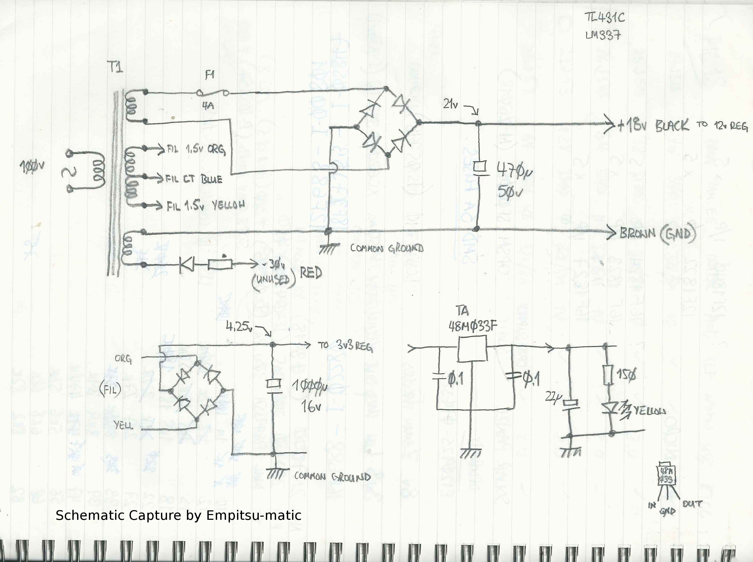
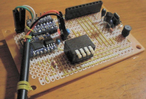
The hardware is very basic. I'm using 200mm, 700RPM, 12v fans to move the warm air through the ducting. Because they run so slowly, they are also fairly quiet, at just 19db. The fans are slowed down even further by using a PIC18F27J53 microcontroller to provide PWM drive to what is effectively a very simple switching (Buck) regulator from a 21v supply. Why 21v? Because that's what the transformer (salvaged from an 80's vintage radio/cassette deck) outputs.
Temperature sensing is courtesy of a handfull of DS18S20 one-wire temperature sensors. Why the (fairly ancient) DS18S20? Because I have close to a metric ton of the dang things sitting in my spares box, gathering dust..
Communications between the remote sensors and the central microcontroller and button/display interfacing were going to be handled by a couple of satellite PICs talking to the master over an I2C bus (hence the daughter boards in the photograph). However, things have taken a turn (hopefully for the better) with the introduction of the ESP8266. I have a couple of ESP-03's and a couple of ESP-12's (and have wasted entirely too much time playing with these wonderful little gadgets) and now plan to put remote sensors and LCD displays on walls (which no longer have to be within a few centimetres of the PIC18) in rooms throughout the house.
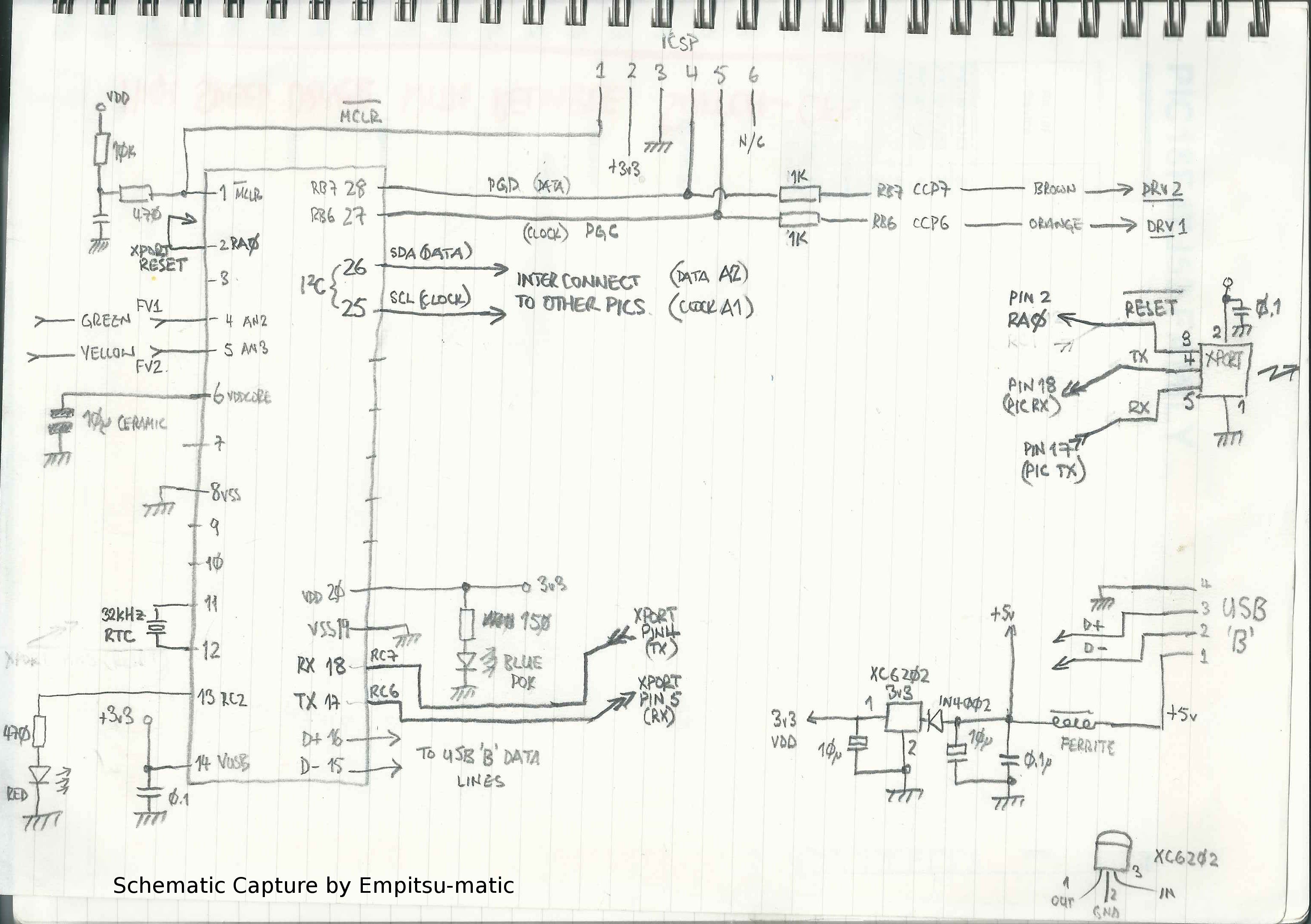
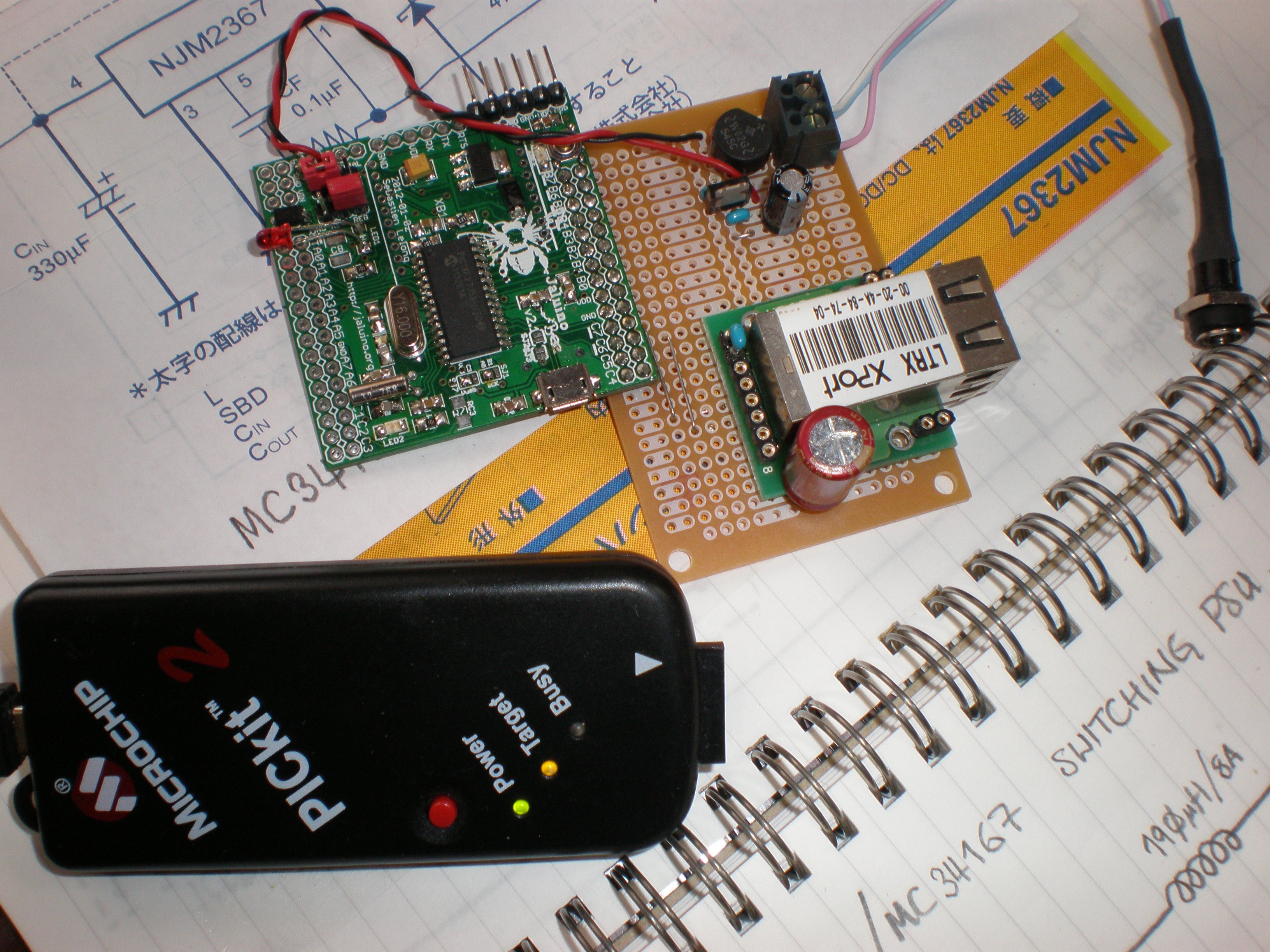
The PIC18 was, up until now, talking to the world via a Lantronix XPort (why? same story ...junk-box) even though it consumes a considerable chunk of power and heats the room almost as well as the woodstove. However, that too is due to be replaced with either another ESP8266, or a Wiz 5100 (I still rather favour the latter, as a hard-wired connection to the central PIC18 would be preferable and the Wiz 5100 compares very favourably to the ESP8266 in terms of power consumption when communications are active).
The PIC18F27J53 is nice in that it includes a RTC (as well as a ton of other peripherals and plenty of spare pins), so the idea is that it will have programmable on/off, high/low, normal/quiet settings (accessible via a web page) and also be capable of being overridden by the remote sensor/LCD units if someone wants an immediate blast of warm air, or prefers absolute silence to warmth.
The Software/Firmware:
The current firmware (such as it is) on the PIC18 was written using JALv2. I don't see too many projects on the web utilizing this much underrated language, but it is very, very useful (especially for the smaller PICs). It doesn't have the power, or complexity of C or C++, but it has a lot to recommend as a springboard for novice programmers. It is simple to use, easy to pick up, quick to compile and relatively forgiving in the syntax department. Although it also suffers from that simplicity (in that there are, for instance, no pointers), it does mean it has a very shallow learning curve and, generally speaking, all of the lessons learned when learning JAL will still apply when moving on to something a bit more complex. It is an ideal language people new to microcontrollers and to programming...
Read more »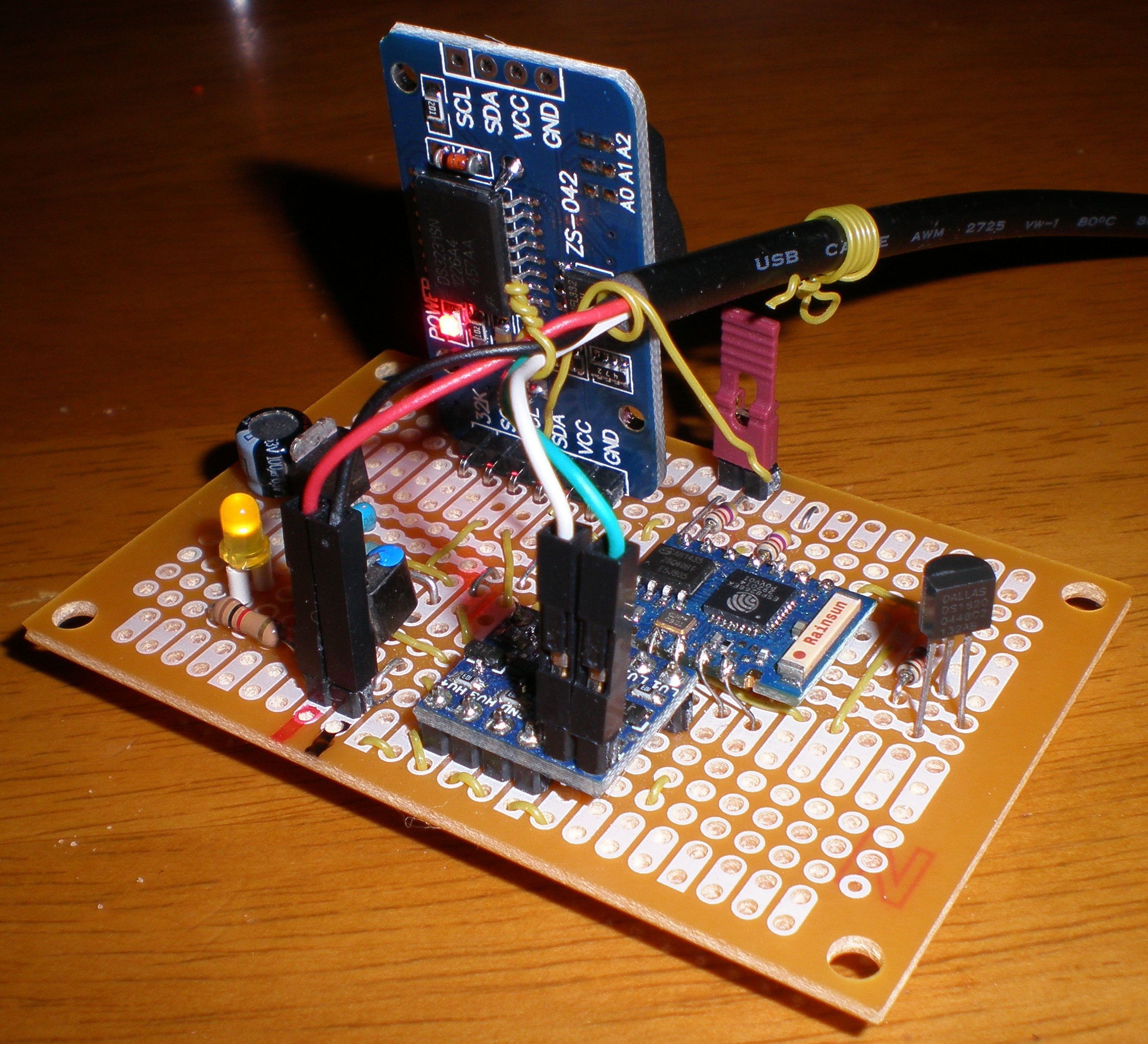
 Xasin
Xasin
 k
k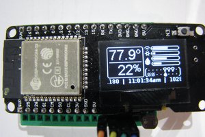
 Jeff Taylor
 AVR
AVR