This track is a 3 lane version; however this design should work fine with minor modifications for up to 6 lanes (6 analog pins on the ATMega48).
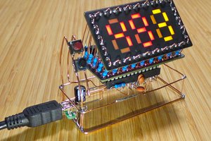
Each track has a 4x 7 segment display, each of which is driven using a 74595 shift register (each one chained together and driven using hardware SPI). The core if the system is an ATMega48 AVR. The timer start button is a push switch rigged into the starting gate; the finish sensors are IR photo transistors above IR LEDs embedded into the track.
It is a fully enclosed system: no requirement for a computer, USB, or anything other than power. This was a conscious decision made to keep the required operator skill level as low as possible. If running an entire race with multiple heats, you can keep track of everything in a spreadsheet (a Libre Office spreadsheet is included in the git repo), or you can just run things for fun and see the times for each race.
The timer has a resolution down to 10ms, and can go up to 99 seconds (99.99).
There are only two buttons: the start button (hooked into the starting gate), and the stop / reset button (on top of the timer enclosure). The race starts when the starting button is released (when the starting gate falls). Each track timer stops when the car passes the sensor. Once each of the tracks is finished, pressing the reset button (on top of the timer enclosure) will reset everything to 00:00. To manually stop a race (if, say, a car did not finish the race), you can hit the reset button once to stop the race and again to reset.
The track, timer enclosure, etc (i.e. everything that is not the timer circuit) was made by the cub leader, and not included in the scope of this project.
 The Big One
 Emilio P.G. Ficara
 danjovic
 Paul Gallagher
 Scott Clandinin