 SHAOS
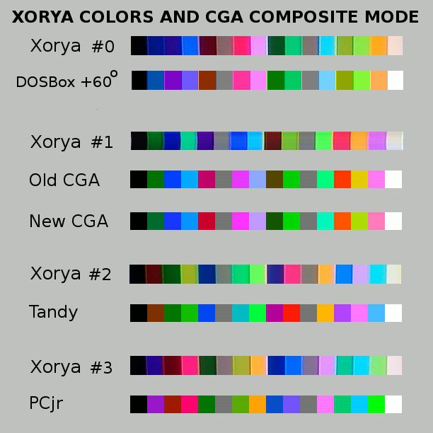
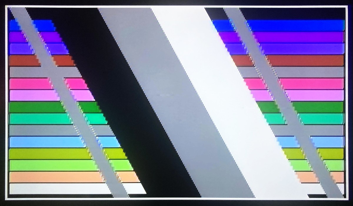
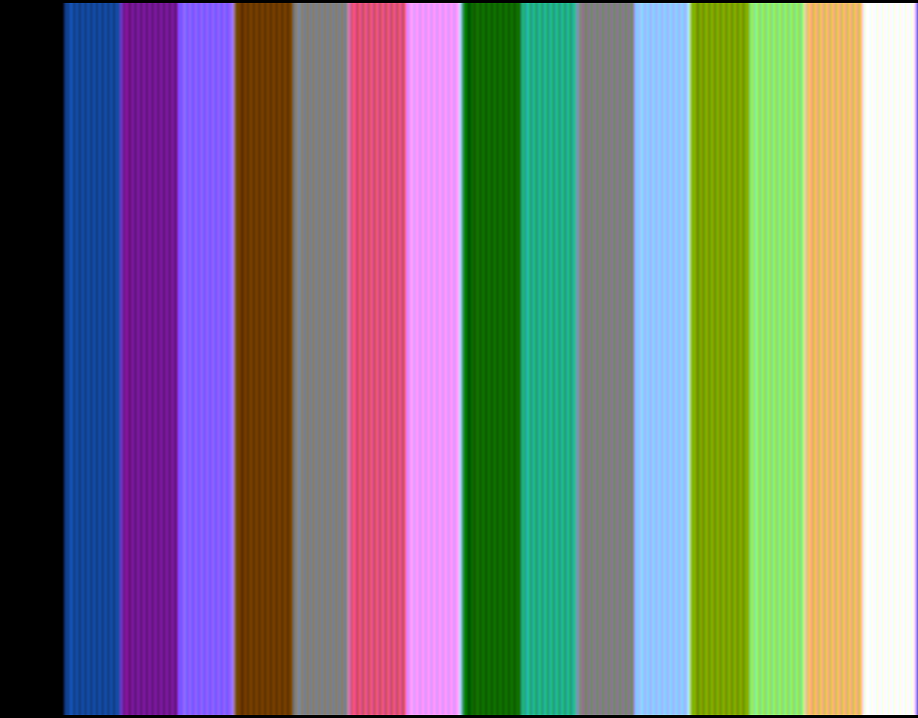
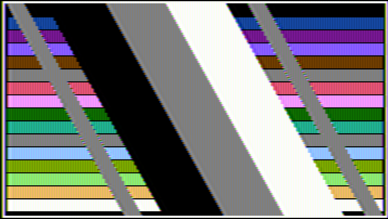
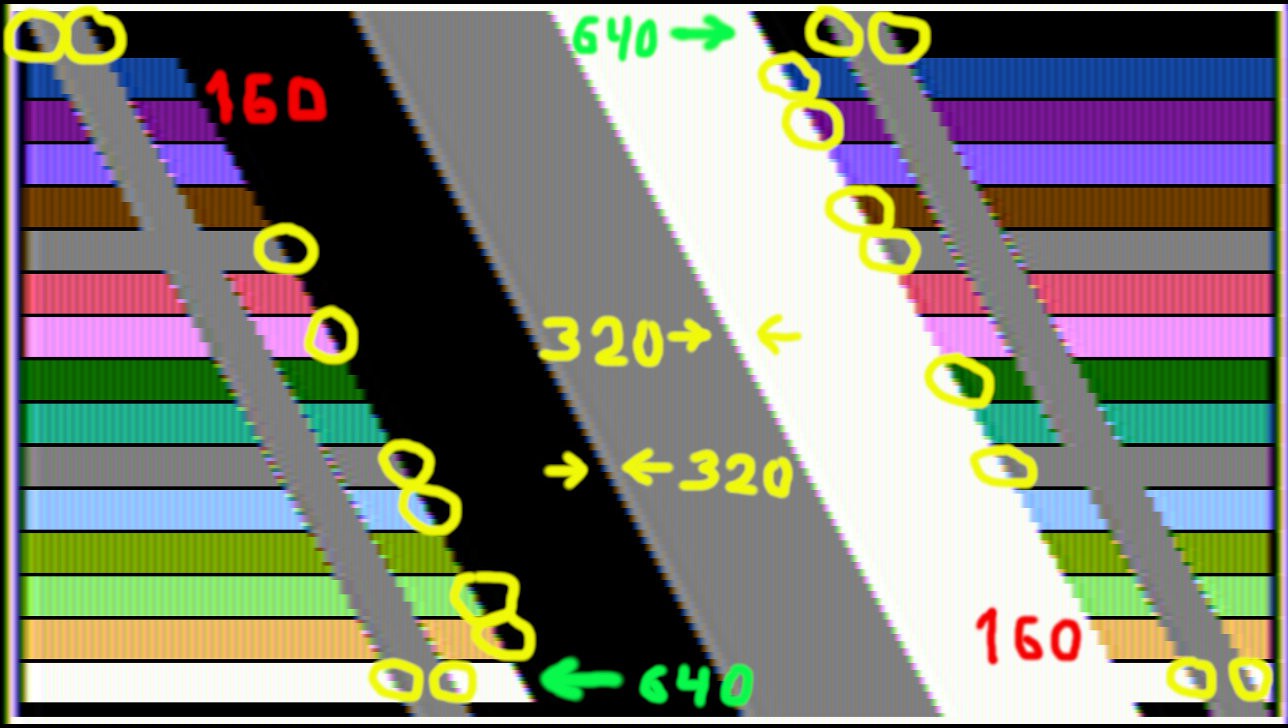
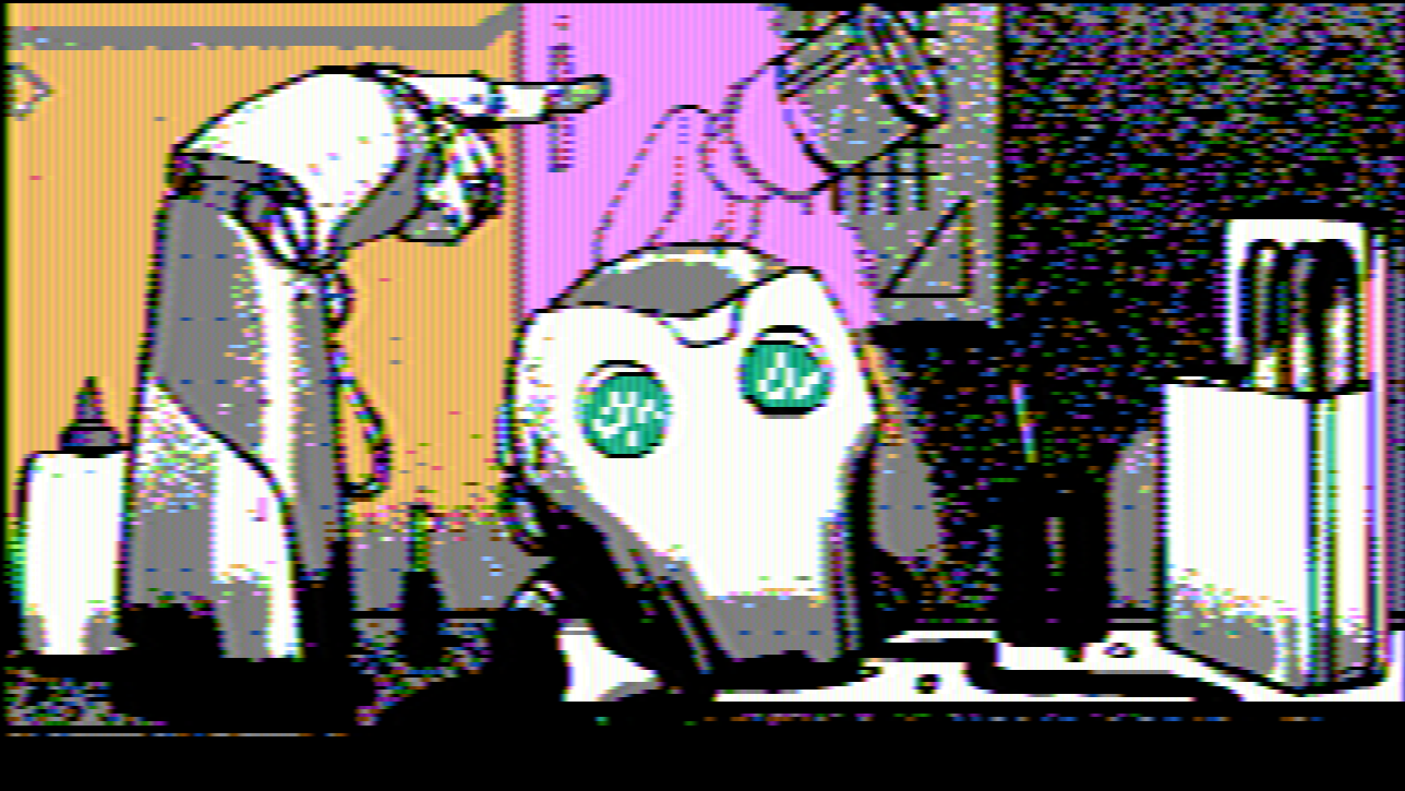
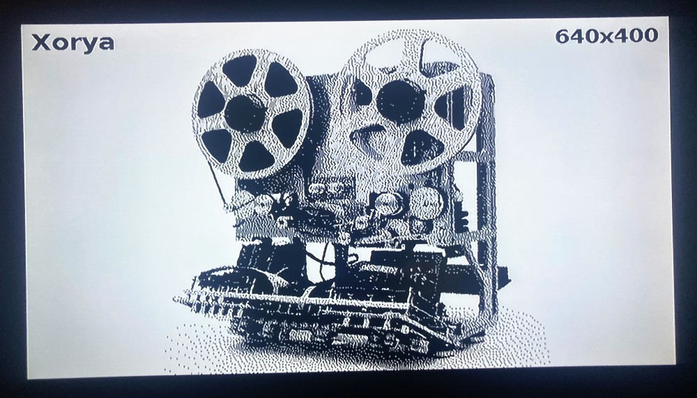
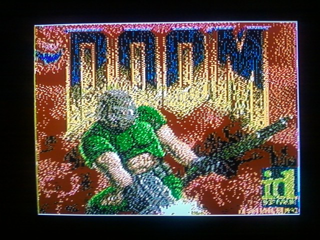
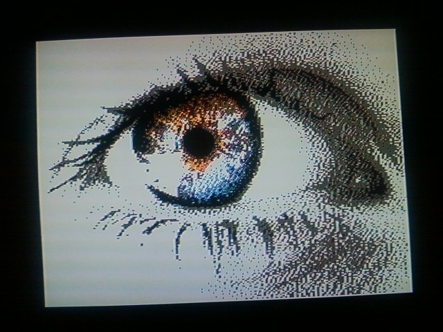
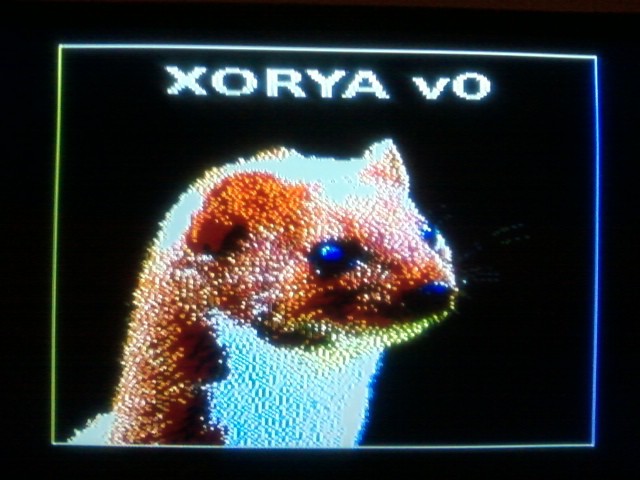
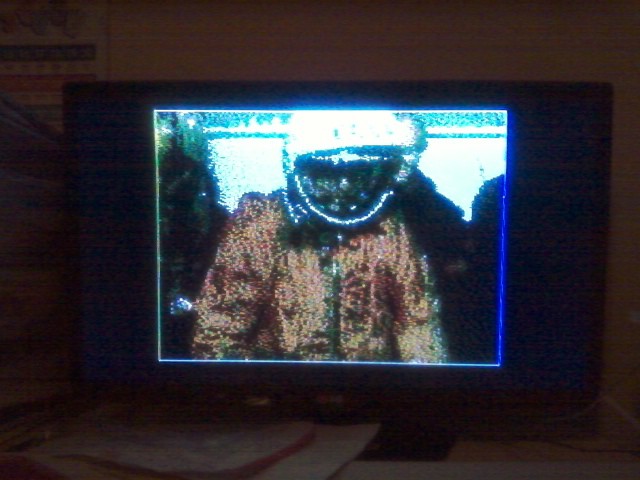
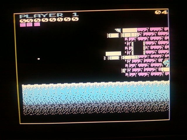
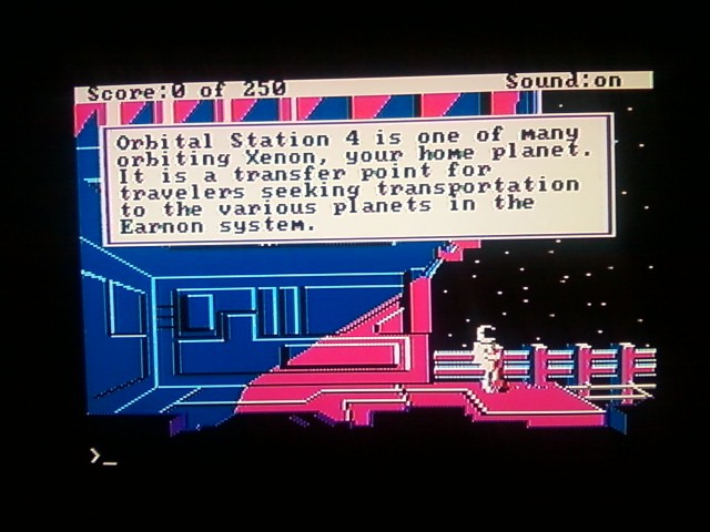
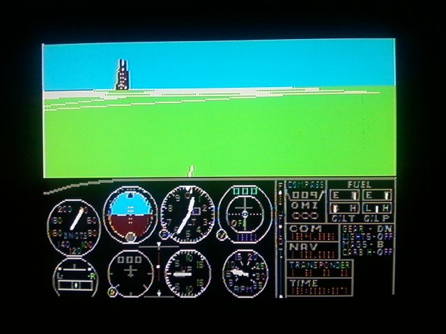
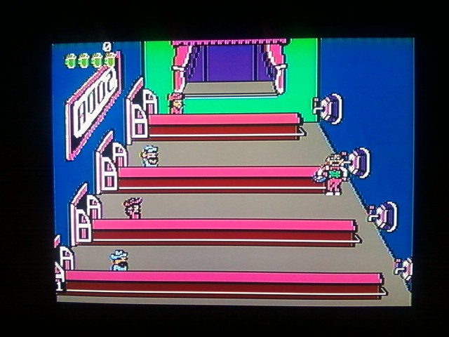
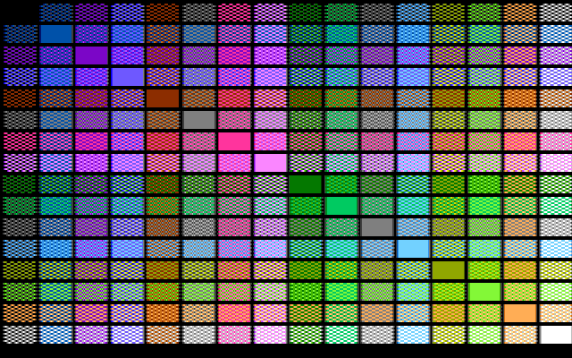
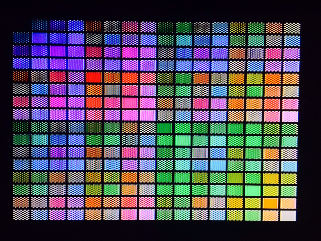
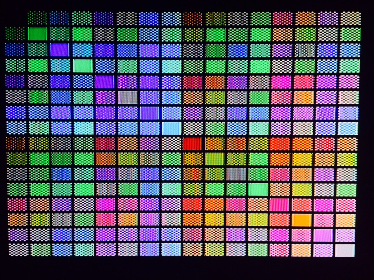
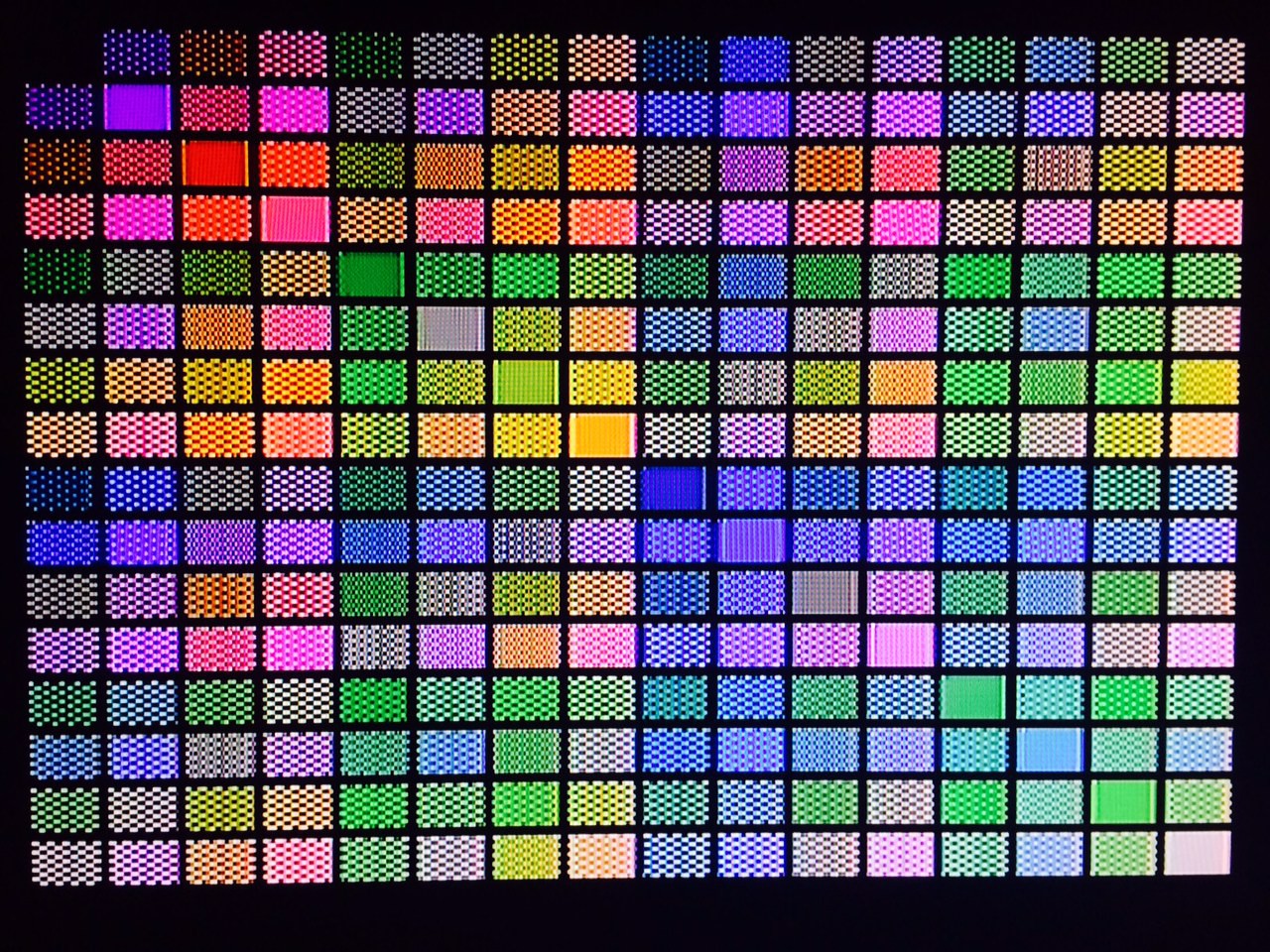
SHAOSProject is based on "NTSC TV interface" examples from http://hackaday.io/project/2032-pic32-oscilloscope by @Bruce Land (Cornell University), which are based on examples from "Programming 32-bit Microcontrollers in C: Exploring the PIC32" by Lucio Di Jasio. I switched text mode to my own 8x8 font and eventually dropped support for original 256x200 resolution and focused on newly introduced 320x200 and 640x200 video modes. Adding color to generated NTSC signal was inspired by KenKen's work, but nothing from that software/hardware was used here because goal of my project was not about getting perfect colors, but to get simplest (and cheapest) circuit that generates a number of distinguishable colors on NTSC TV. Accidentally I reinvented "composite mode" used in earlier CGA (when every 4 black and white pixels in the row confused NTSC TV to detect different colors depending on pixels pattern) with the same resolution 160x200 and very similar palette (actually 4 palettes of the same 16 colors are supported: 0 - original XORYA palette, 1 - palette similar to CGA composite mode, 2 - palette similar to Tandy composite mode, 3 - palette similar to PCjr composite mode, where "similar" means color phase is shifted back about 30 degrees versus original):
To make video memory compatible with CGA I also changed 32-bit DMA-to-SPI to 8-bit (because SPI sends higher bit first and in case of 32-bit it works as big-endian, but it has to be a little one) and surprisingly it did not negatively affect performance (text mode even became 43% faster because now it is not required to mask single byte in the word to write a character). And before adding project here the progress was reported on DangerousPrototypes forum.
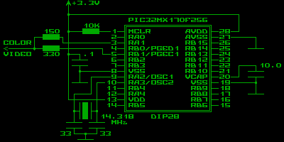
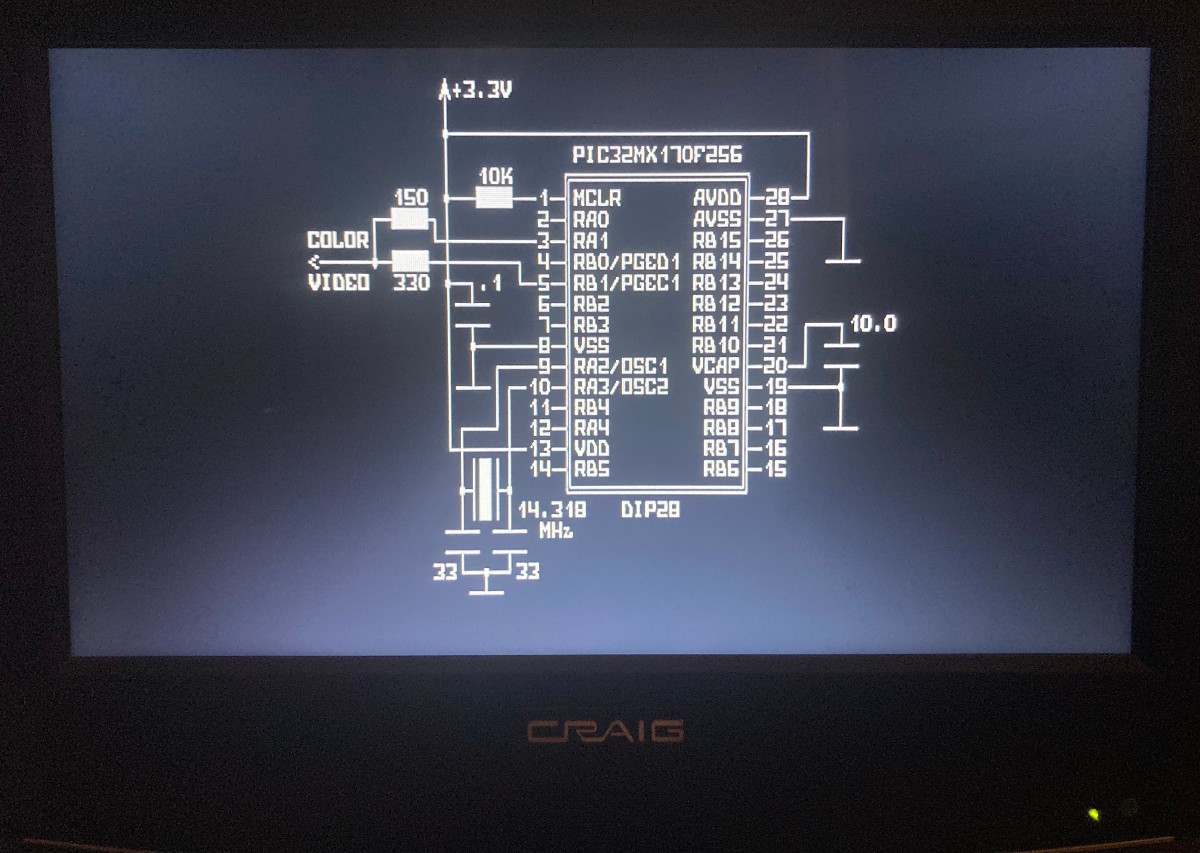
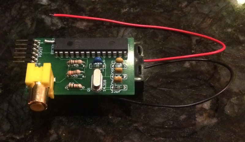
Current schematics (for generating color NTSC signal, no audio or inputs yet) with external crystal 14.31818 MHz (it must be precise):
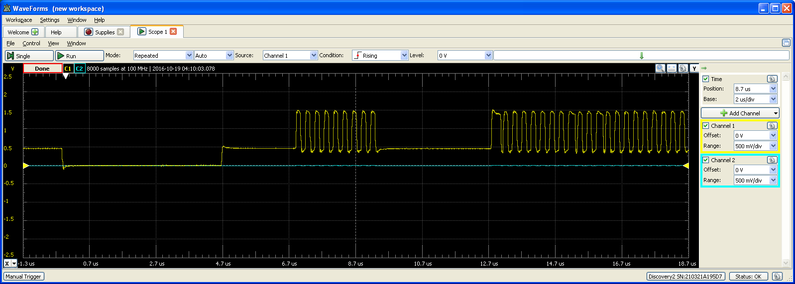
It generates this waveform with "color burst" in the beginning of every line:
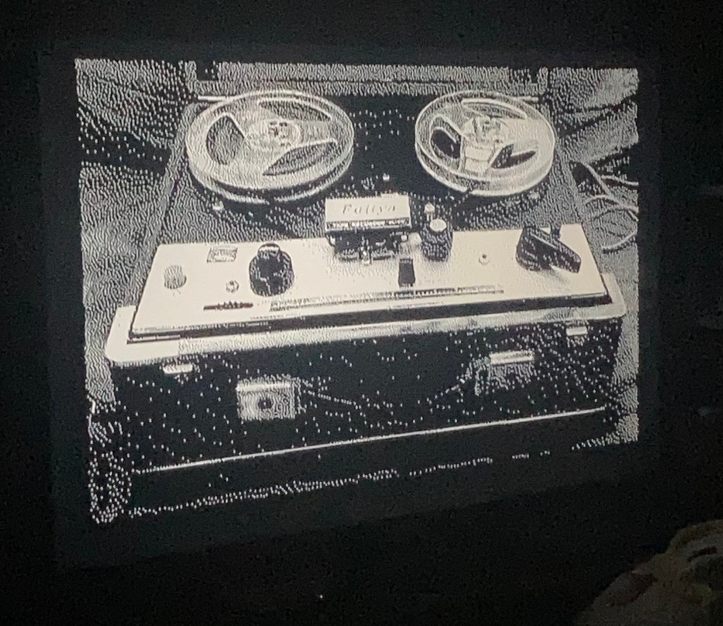
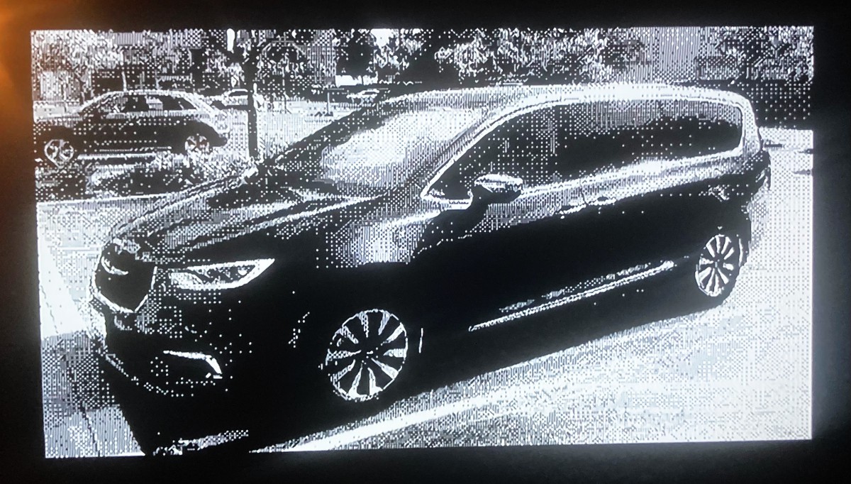
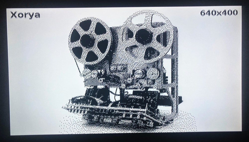
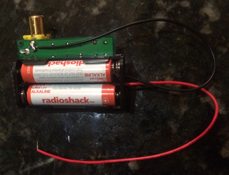
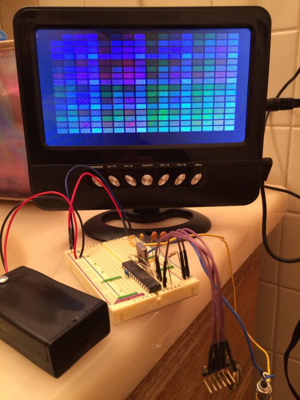
Simplest Black-and-White NTSC version (no color) with internal oscillator: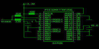
This version is a little bit faster because it's running on 60 MHz core frequency instead of 57.27272 MHz as previous one.
Also note that 6-pin header is required if you need to reprogram the chip by PICKit3:
- MCLR (pin 1)
- 3.3V (pin 13)
- GND (pin 8)
- PGED1 (pin 4)
- PGEC1 (pin 5)
- Not connected
To build something with XORLib you need MPLAB.X IDE and XC32 compiler (but NOT new one, it has to be v1.34 or older because of plib.h - old versions could be found here ).
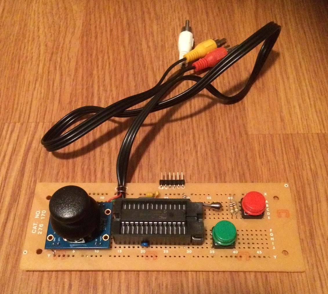
Cheapest possible implementation of Xorya is Xorya Touch where controls (both gamepad and buttons) are drawn by copper on PCB itself...


 zpekic
 PK
PK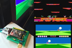
 rossumur
similar arduboy ?
Meybe add big screen 3-4 inch
joystick , 24 h working time, (meybe ad solar panel)