 Joshua Young
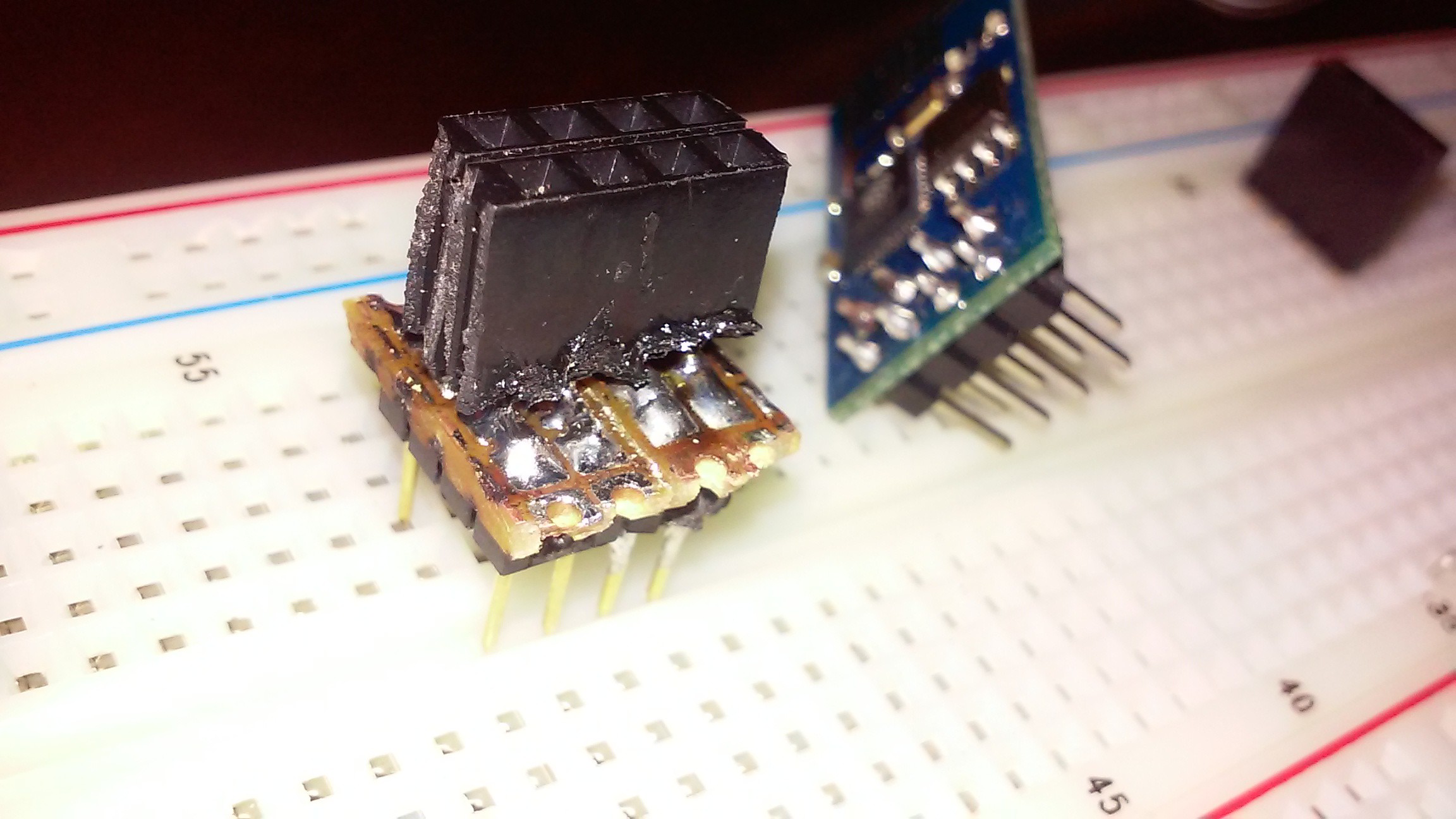
I would like to give a little more detail on my progress so far. The first hurdle I had had was connecting the esp 8266 to the board, easiest way to protype this thing chip is to make a breadboard connector so you can hook the chip up the the wider pin spacing. After some tight soldering I was able to get my adapter working.
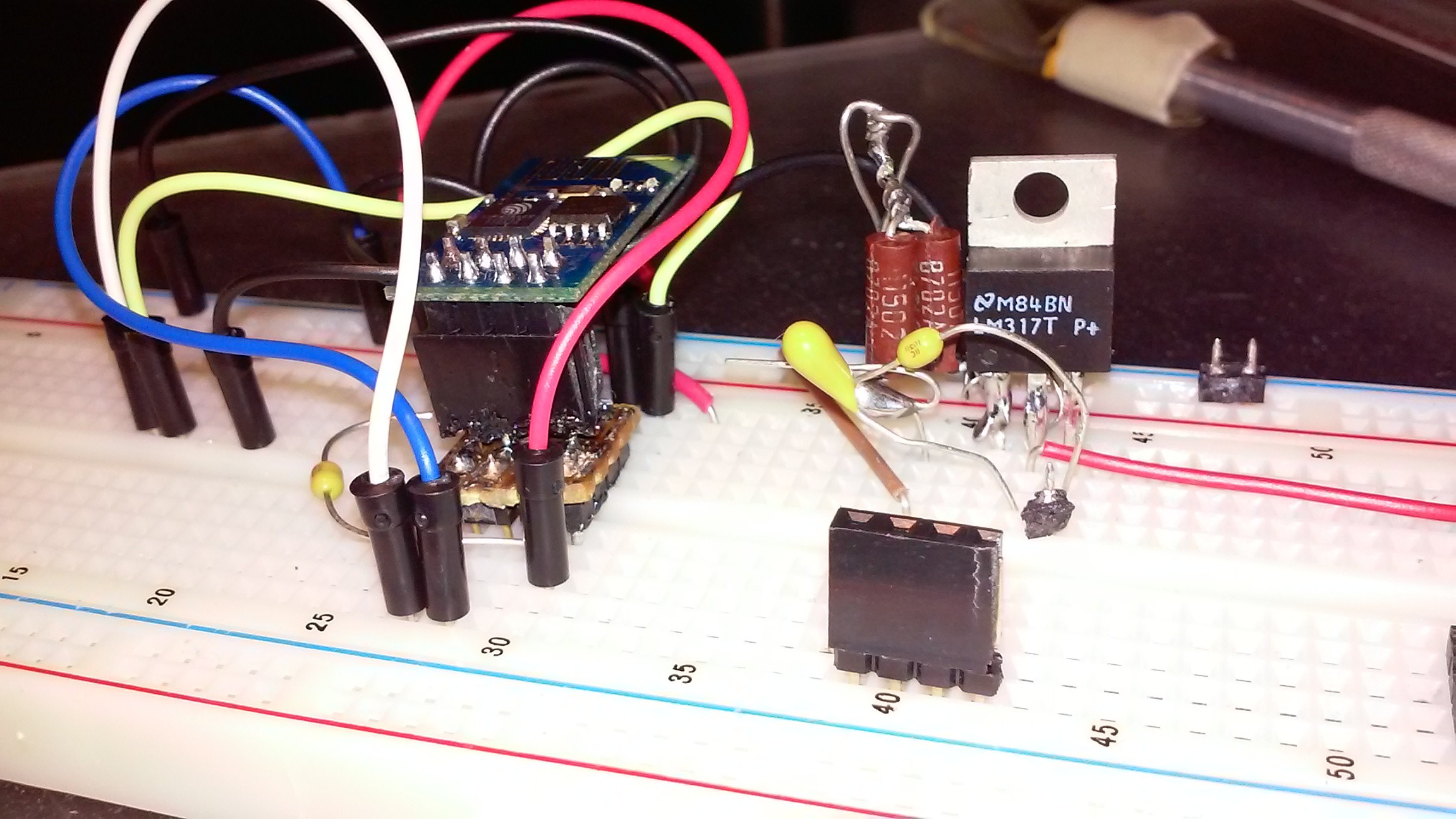
Once I had a way to hook up to my breadboard, the next step was to get my ESP power supply working. To do this I needed to make sure my FTDI chip could communicate with my ESP 8266 and that the ESP had a stable 3.3 volt power supply. I used a LM 317 with the appropriate resistors and capacitors called out on the data sheet and was well on my way.
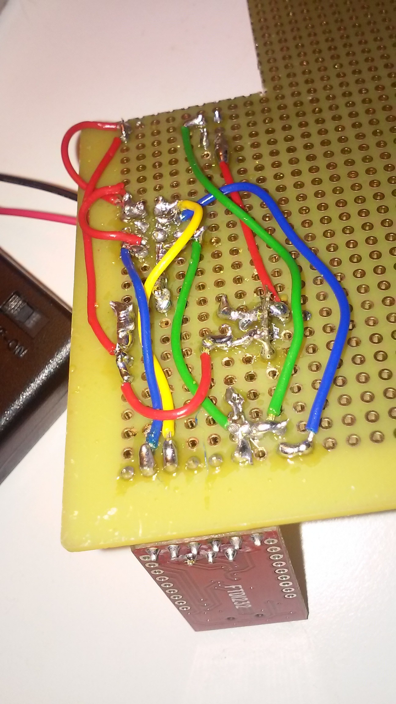
Still the board was misbehaving quite a bit. I looked into this issue and found that breadboards are too inconsistent to reliably test these type of chips. That meant the next step was to move onto a soldered proto-board. I added a DC power jack to the board so I could power the system with a simple 12 v wall wart. I got all the components in place, but could not get the system to work. Turns out I had a solder bridge, that was not showing continuity on my meter, but was contacting occasionally when energized. Re-soldering the joints and re flashing the chip verified this suspicion after many, many failed flash attempts.
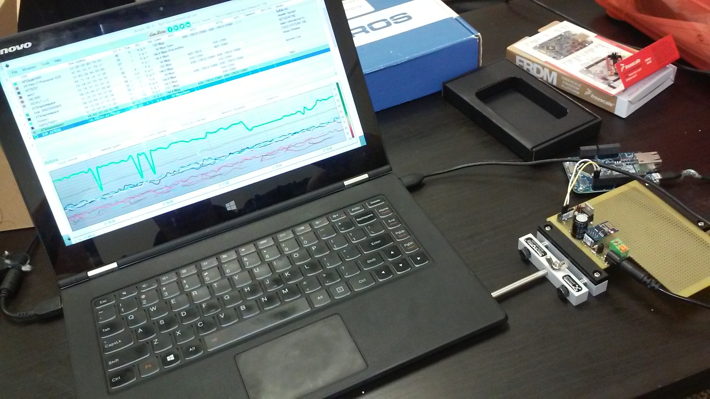
I wanted to analyze signal strength and consistency and found Acrylic WI_FI Free to be a pretty good tool to log this.
Discussions
Become a Hackaday.io Member
Create an account to leave a comment. Already have an account? Log In.