 Anthony
So that we have our pads/traces setup, the next question is how do we best connect our transistors ?
For a refresher on transistors SparkFun has a pretty good tutorial, including amplifier applications, so here just the basics we need for this project.
Also, keep in mind since we are only interested in the switching characteristics you could use either NPN or PNP transistors for this project. NPN just seem the more intuitive to me when used for a simple switching application.
Personally, I think some tutorials get into too many of the possibilities or potential uses of transistors up front (though the additional capabilities are well worth learning about), and it thus makes a bit confusing as one starts thinking, should I use NPN ? PNP ? What's the difference ? Base, Emitter, Collector !?! What does it all mean !
For a case where it is used only as a digital switch, either is type isfine, as long as it is oriented the proper way (more on this in a minute).
The way I choose to see it is rather like this:
- First, do I want the switch to be 'on' (short-circuit) when the signal from my Raspberry Pi is :
- 'high' / 'on' / '1' / 3.3 V -- Then choose NPN - or read 'NPN' as 'on when positive'
- 'low' / 'off' / '0' / 0 V -- Then choose PNP - or read 'PNP as 'on when negative'
- Thus it is the 'middle letter' that determines the switch state 'on' configuration.
- Please note the above are only ways of thinking that I have found to be useful mneumonics: 'N' and 'P' above actually stand for 'negative' and 'positive', and thus the term 'bi-polar' transistor, as at least two poles are the same. Tech Note: For the particular transistors we will use in this tutorial, this also further simplifies in so far as of the three transistor legs, the 'switching (i.e. on/off)' or 'base leg', as we will get to the details on in a minute is always 'the one in the middle'. However this is not the case for every model of transistor, so always double check the datasheet.

[From now on this 'bubble' will signal a learning point, but also a total digression]
A very reasonable 'thought point' crops up here based on the above. If, simply speaking 'intuitively', when we think of switches, 'on' tends to mean 'it has power', or is at a positive voltage and thus at a 'high' state (more the terminology most commonly used with MCU's like the Pi because the actual output voltage may differ. For example, unlike the Raspberry Pi, or Beaglebone Black, an Arduino Uno has a 5V max switching output. In either case though, 3.3 V or 5 V, when the switch is 'on' it is considered the 'high' state.
So, okay, I am trying to design a circuit with a switch, why on Earth would I like to confuse myself by selecting 'PNP' (on when negative, or voltage zero, 'low' state, versus 'NPN' ?).
Well, PNP does have some additional properties that at the more advanced level are more suitable than NPN, but we can also bring this question right into focus with the RaspPi.
In this project we will be using an AC adapter to power both the RaspPi and the additional, call waiting, etc, functions of the phone that typically require batteries.
I mean, yes, you could use the in-built battery box to power the whole subsystem itself, but the phone itself has an ultra low power MCU on board, as after all it really doesn't have to be 'always on', or process natural language, only interpret some basic data to a low power LCD.
The RaspPi, however, while it certainly can be run off AA batteries, is decidedly more power hungry. Obviously, having to change out batteries < every 24 hours is completely unsuitable for an Assistive Technologies type device.
Yet, let's say we wanted to use the RaspPi for some other project and wanted it to run both continuously and on only battery power.
A couple of points here crop up, first and foremost is that the RaspPi, unlike most Arduinos, is only driven presently by a very narrow power supply range of 4.75 - 5.25 V, thus, admittedly for this conception to be a 'true reality' one should also look up the topic of voltage regulators.
(I wasn't really happy to find a tutorial I really liked on this subject and may decide to cover the topic later when we get to it. For some basics, again this tutorial by Sparkfun [scroll down a bit], or 'The Bald Engineer' also has a much more through and comprehensive [though more complicated] treatment. In my mind the important point here is a 'voltage regular' is the perfect easy choice, if say 'six standard AA batteries, well that's 6V total ! ... But for my project I need basically an average of 5.
In that case, a voltage regular is your very simple and easy choice. One might even push the level up to 12 volts.
*But*: The really important thing about voltage regulators is the only means they have of going from a very 'large' voltage 'to a low one', is by distributing all that excess power as heat.
This could be 'very bad' for one (though nearly almost any electric component can start an electric fire, even simple resistors), but secondly anyone who has studied entropy, worked with the efficiency of gasoline engines, or really, even looked and felt the warm glow of the sun (though we presume it is not there for a design or purpose, so an exception), knows that basically 'waste' energy, or not producing a particular 'directed force', is released as 'heat'.
At least from a general 'engineering' point of view, depending on the area of study (i.e. in Metallurgy we obviously need heat for certain processes, but in engines as in electronics it tends to signal waste) , excess heat can suggest lower levels of efficiency.
I don't mean to go into so much detail here, but I should also be honest with myself that the vast 'majority' of complete XYZ tutorials for beginners available are based around 'buy these specific parts', where I have no monetary interest here, so I would like to promote learning + not blowing yourself up.
But, for the thought exercise, let us presume we were using a traditional '7805' regulator, available from many manufactures and vendors-- kind of like asking 'I want a compact car'. The particular version selected can handle up to '24 V' input, but we basically want the 5V output.
So... Where do the transistors come in ?
First, let's say we wanted (needed) our RaspPi to run 'continuously', but only via battery power... Eventually, at some point, the above cited example would simply 'run out of power' and everything would shut down, we'd have to replace the batteries, reboot, start all over... But, imagine for a second we had 'two banks' (and with a heavy regulator like the '7805' this might not 'actually' be necessary, just have status LED's with a resistor load in-line and replace them when the glow of the light runs low, but this is intended to be a more sophisticated thought experiment).
In fact, we could have PNP type resistors straddling each of the cells between the two banks, such that when the power in Cell 1, Bank 1, runs 'low' [or for most transistors below .6V], it gets a '0', and 'switches', though what it switches to is actually Cell 1, Bank 2 and power is readily restored). So why is this potentially useful ? Well if you also had a circuit with at least integrated indicator lights, you could know, to replace the spent batteries while keeping the fresh one's going, and thus supply continuous power to your device across multiple cells, all the time without risk of 'shut down'.
Aside from this, there are much more 'powerful' examples of why PNP might be used over NPN-- It is not 'just' for batteries, or 'backup systems', but the simplest I could think of towards breaking the 'mental barrier', of why 'off' might actually be 'on'.
Also, let's say you are 'hacking' an established system as in fact we 'really' are now, well what if you examine the circuit, and 'off' actually is already 'on', kind of against convention... Well in that case you have no choice but to use PNP.
Traffic patterns, in a large city grid is the more 'exact' example-- 'Stop' on the West Side, might mean 'Start' on the in a very East distant street, only in modern day electronics these decisions are happening nanoseconds fast.
For this project, we're going NPN (PN2222), all the way. Easy to work with, simple to use.
Further, the last couple of days I have debated myself the most 'proper' approach to this problem for this particular use case., so lets look at the board and an PN222X class transistor and see what we are dealing with:
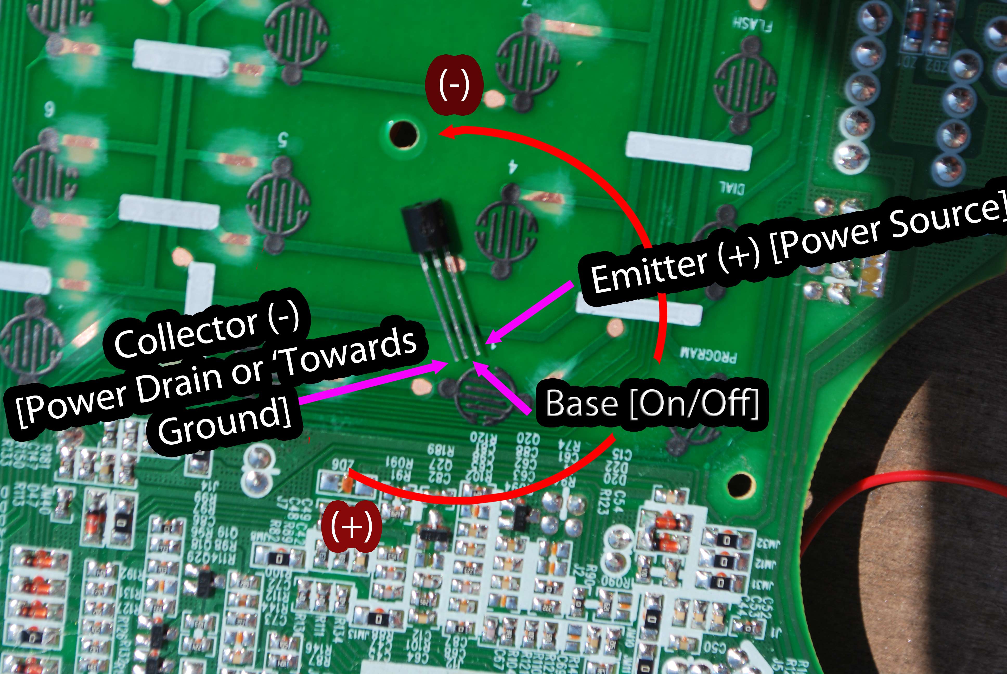
Remember that any through-hole transistor will have a 'rounded' side and a 'flat side' that allows us to establish which pin is which (i.e. left/right) Thus, with the 'flat side down' on the board for this particular transistor [or it was expressed in the digression above but the layout that follows is not universal, but very common] we can basically gather our 'in' or 'out', and our 'switch'.
At this point to fully explain the above diagram it is important to elucidate the two transistor type schematic symbols.
Personally I find this diagram to be very useful:
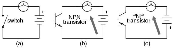
To this diagram I have only added arrows pointing to the 'load' of the circuit, depicted here as a 'light bulb'.
But, imagine for a moment, considering (a), in (b) the bulb were on the 'opposite' side of the circuit, perhaps not by design, but restriction, and thus another argument for 'PNP', vs NPN.
However, the most important thing here to consider, in light of the diagram above, is 'which way' is the current heading ? Is it diagram (a) or (b) ?
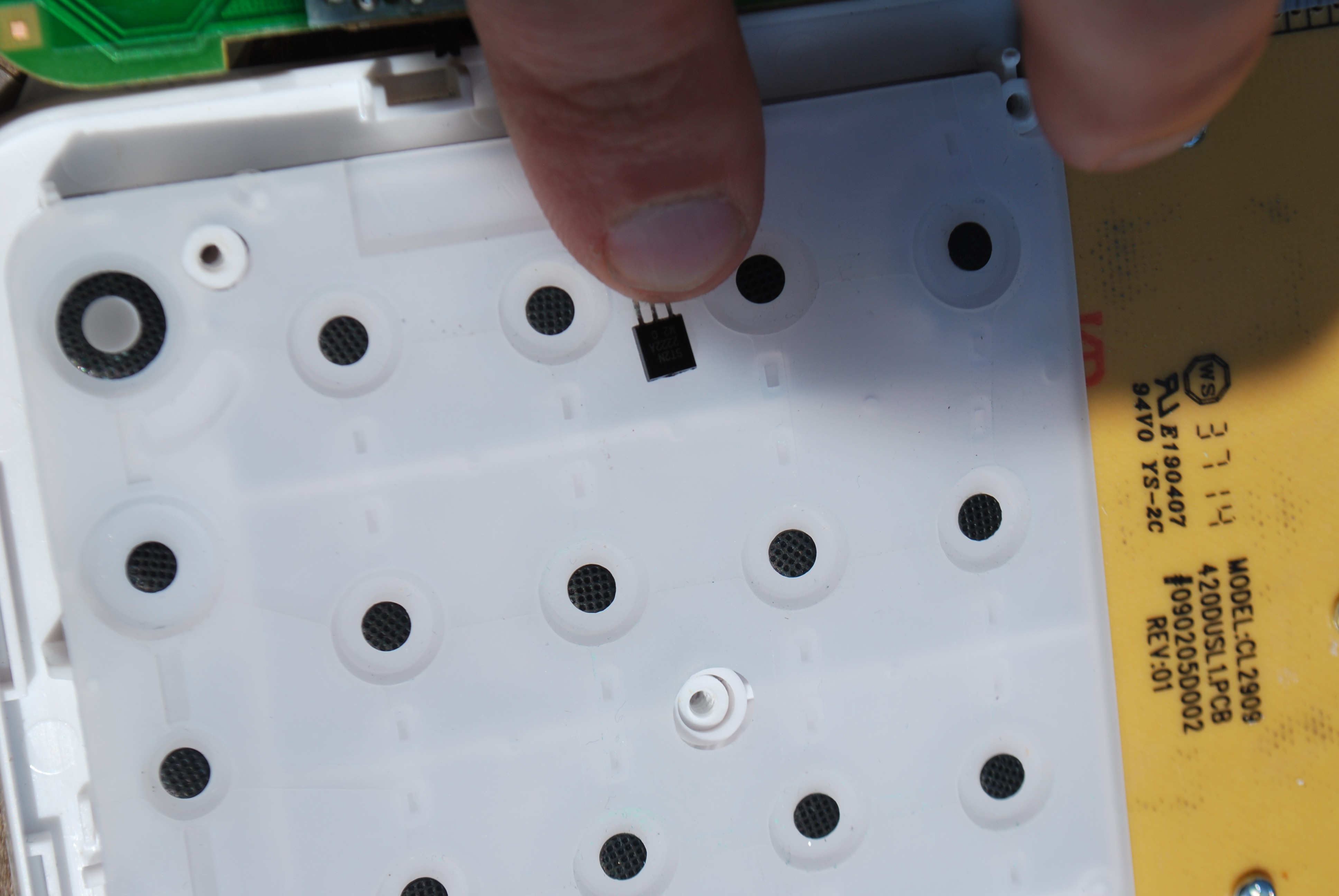
Further, with this particular device, at first I did not figure it would matter, after all the other side consists of 'pilled' buttons and a soft, pliable, silicone pad:
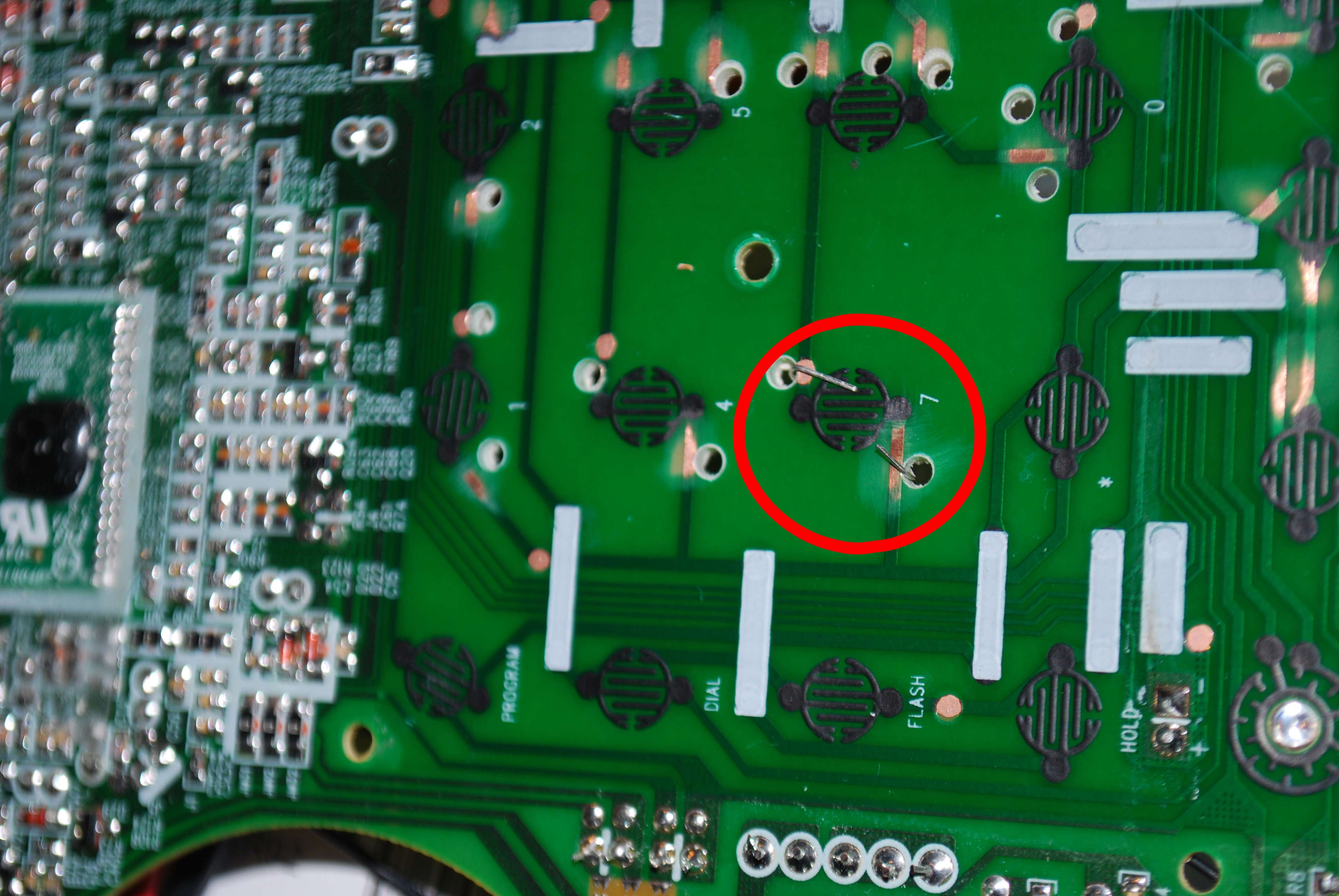
So, I decided on a procedure for board drill out... And to be honest it is very rare it occurs, like this, that you are facing a 'one sided board'... So the 'easy' way to check is to hold it up to the sunlight:
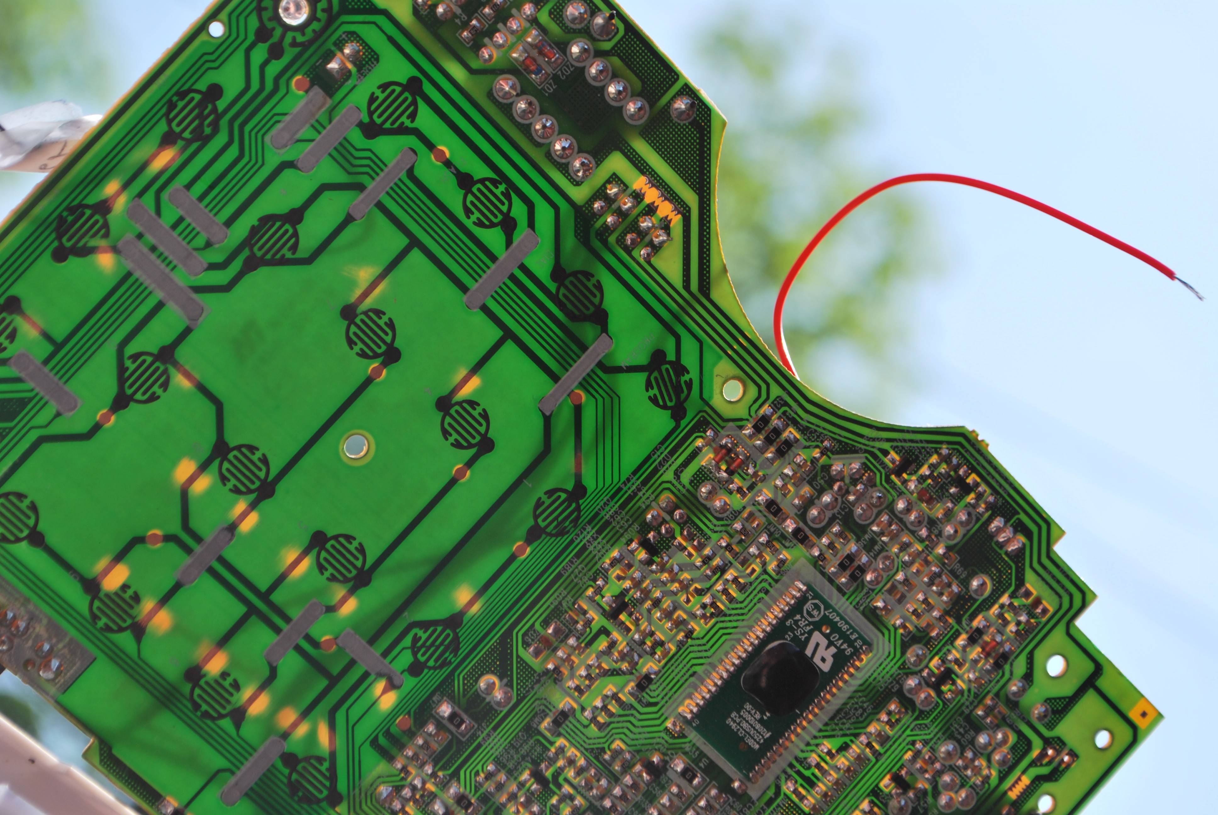
While there are a few points where one can notice 'one stripe' as the undercurrent of two, anything 'more in depth' and you have to rely on X-Rays, an other methods most us don't readily have available to us, but yet this particular 'sun test' result is amazing, great. means we can work with it....
Only a few of the traces on this board are embedded very tightly.
I found the smallest bit I could in the shop [and still, I imagine it is 1.6 mm at best], but it is still much too large to fit through the maze of certain traces needed here]
Also, always wear eye protection when working with small bits, as they will shatter very easily.
An example of where I am at the moment:
But further details will have to wait, actually, for my own editing/development session later--
Discussions
Become a Hackaday.io Member
Create an account to leave a comment. Already have an account? Log In.