Close
0%
0%

Evolution of My Coil Gun

I have found researching Coil Guns tends to be either too little or Too Much information So I am going to Document my builds as I experiment

Similar projects worth following
As I go from initial proof of design to full functionality and higher power. I am going to try to document materials and data as well as the logic behind attempts in the design.

Basic concept of a simple coil gun design.

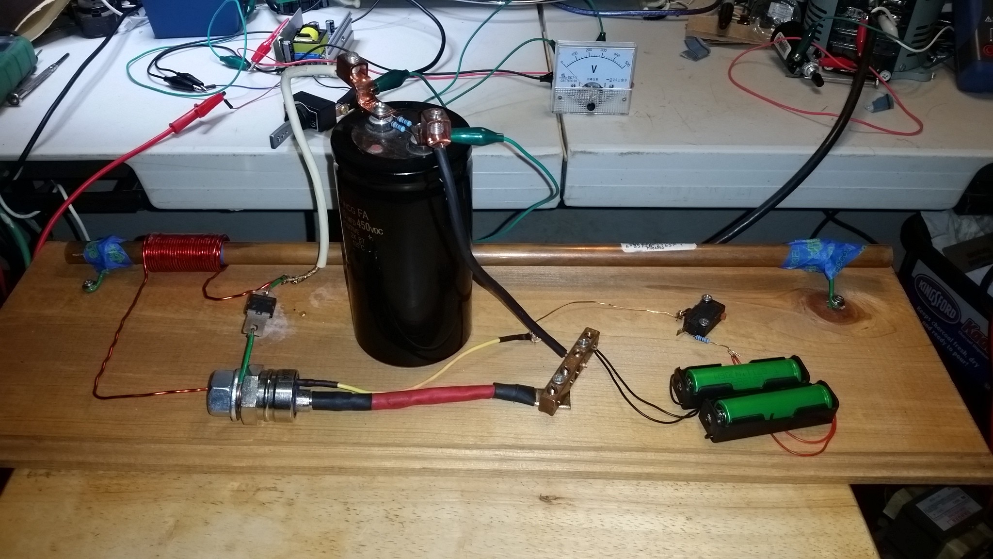
A capacitor discharged through a switch into a coil with a Diode in the loop to protect the capacitor. The Magnetic Field generated in the coil will accelerate a metal slug. Most people desire to generate enough kinetic energy to pierce a can or box of cardboard.

Then there is some method to charge up the Capacitor.

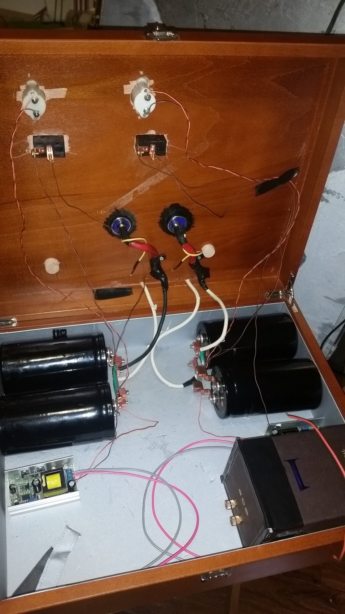
The other side of the circuit is some way to power up the system. I initially looked at rectifying a Microwave Oven Transformer (MOT) using a Variac to tune to the correct voltage. This method was pretty effective but I had a dc - dc 12v to 450v converter that worked at 40w. So I found it easier to power my setup from the bench supply with an end goal of a battery bank.

OK- so That's the too little information - lets expand a little

Usually at this point most posts will start to get really technical and say a bunch of times hey THIS WILL KILL YOU - Yeah kids, you need some real concepts of how electricity works before messing with the High Voltage side of these , because our big Capacitors throw more than enough amps to Kill You. but the rest of us always say DUH Now tell me something. OK

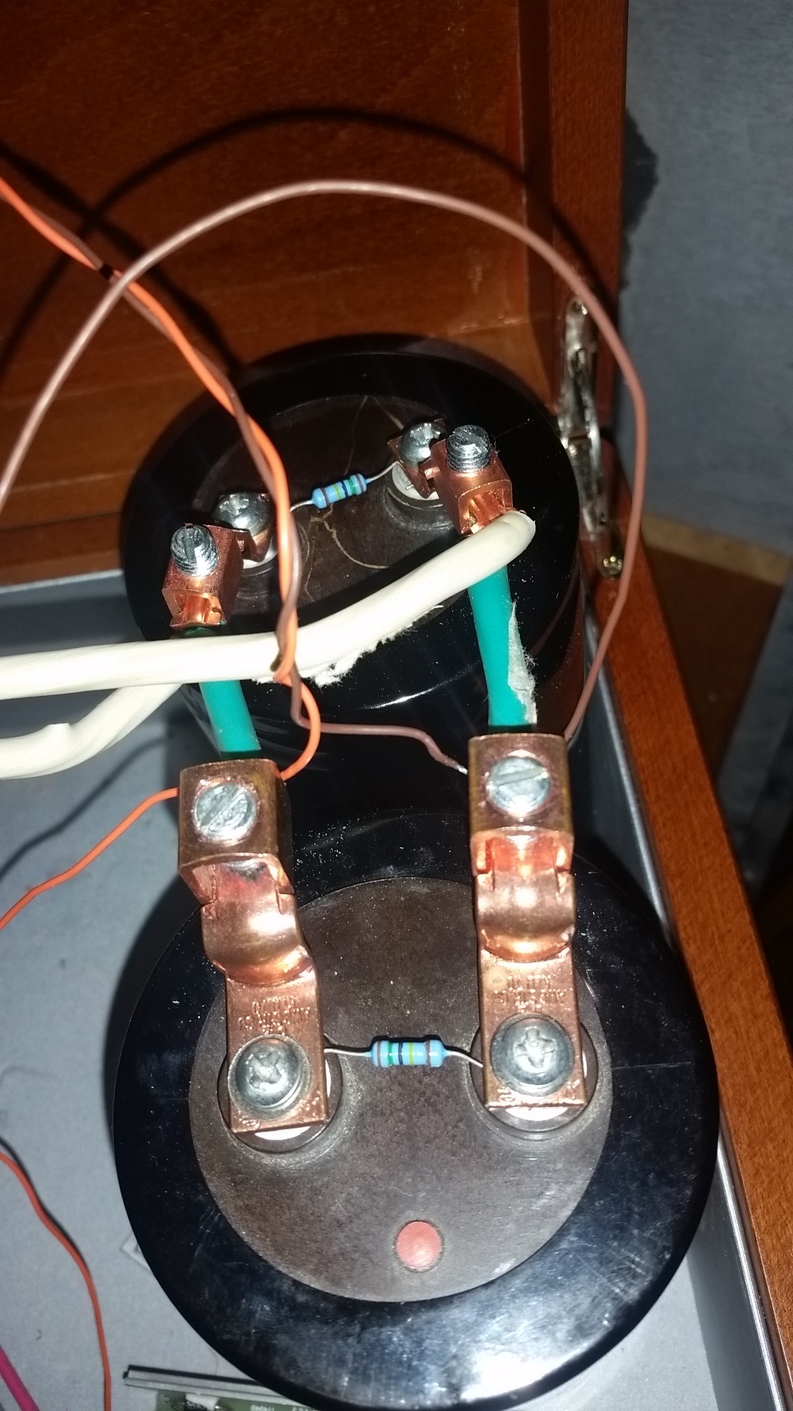
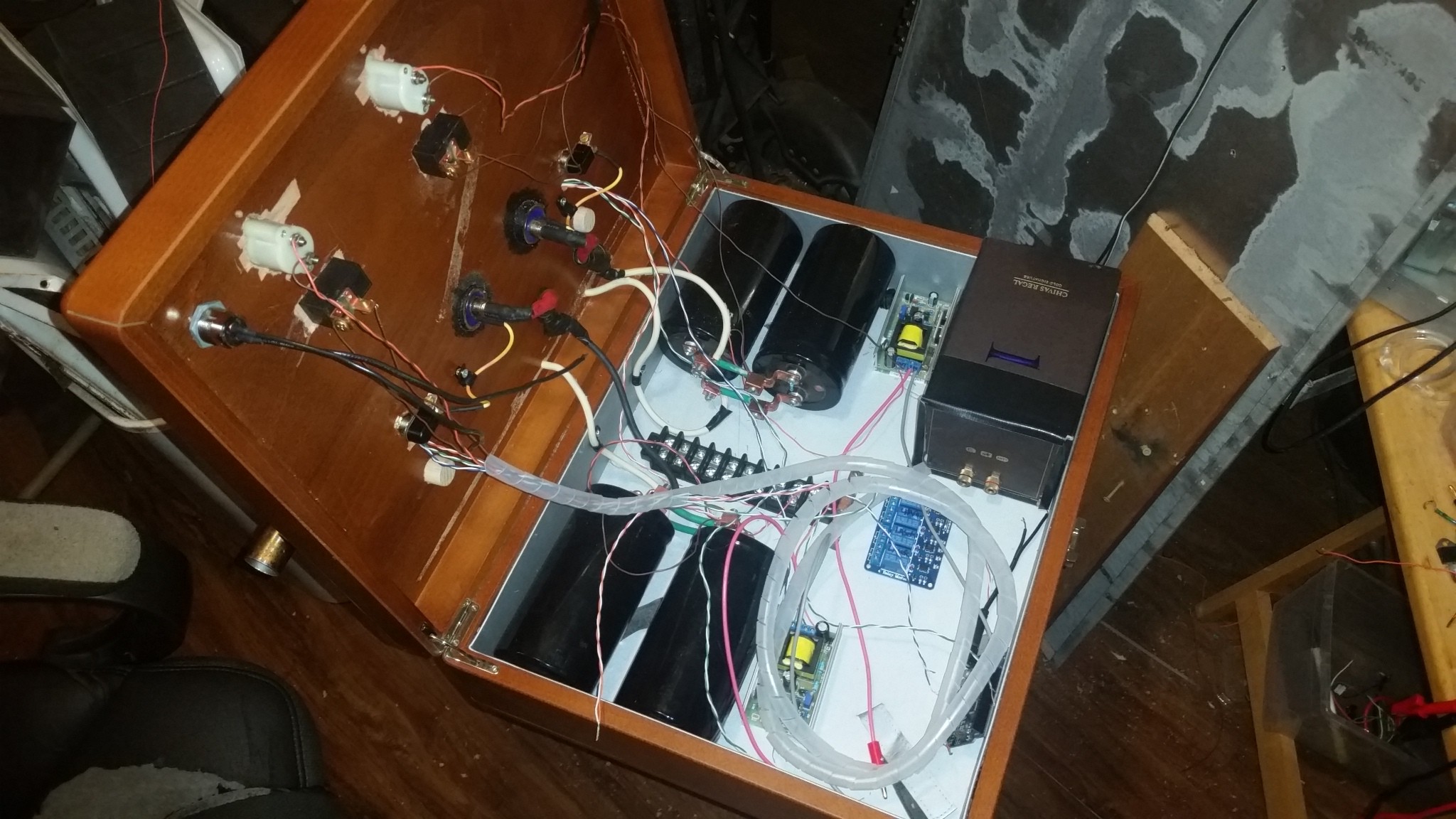
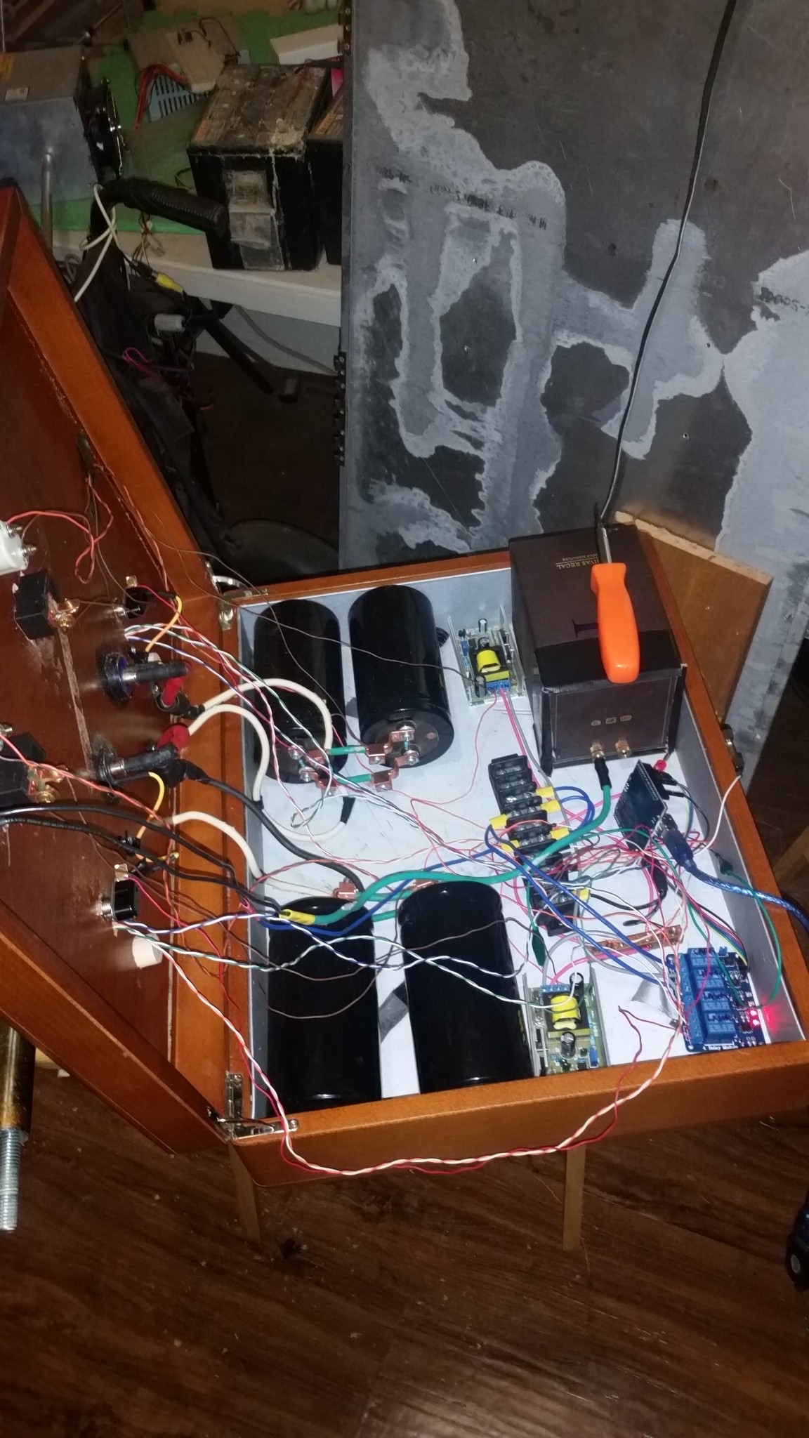
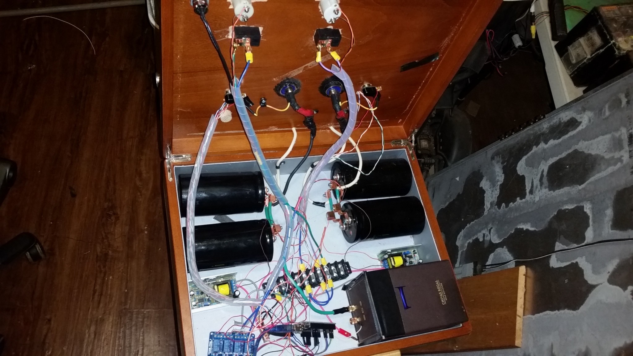
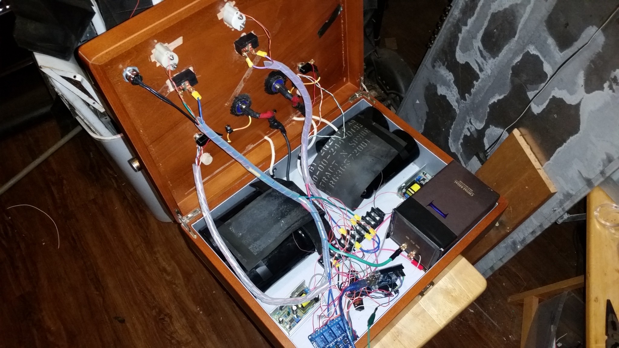
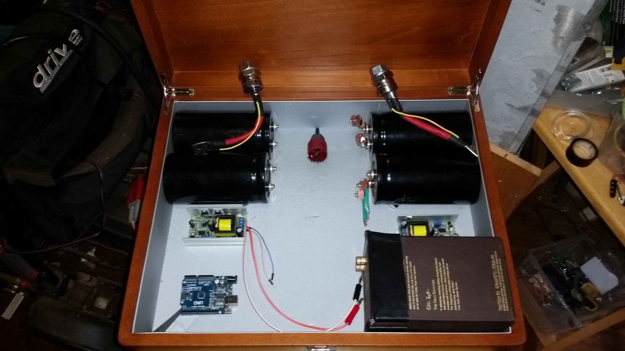
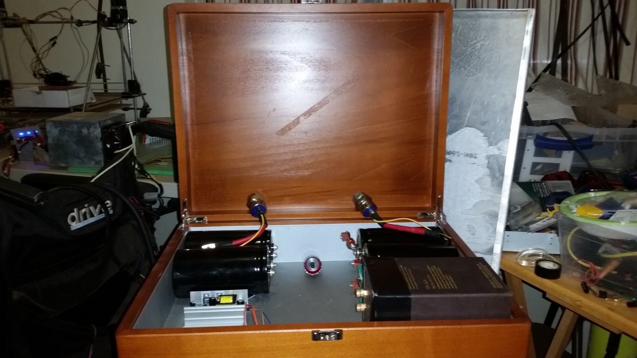
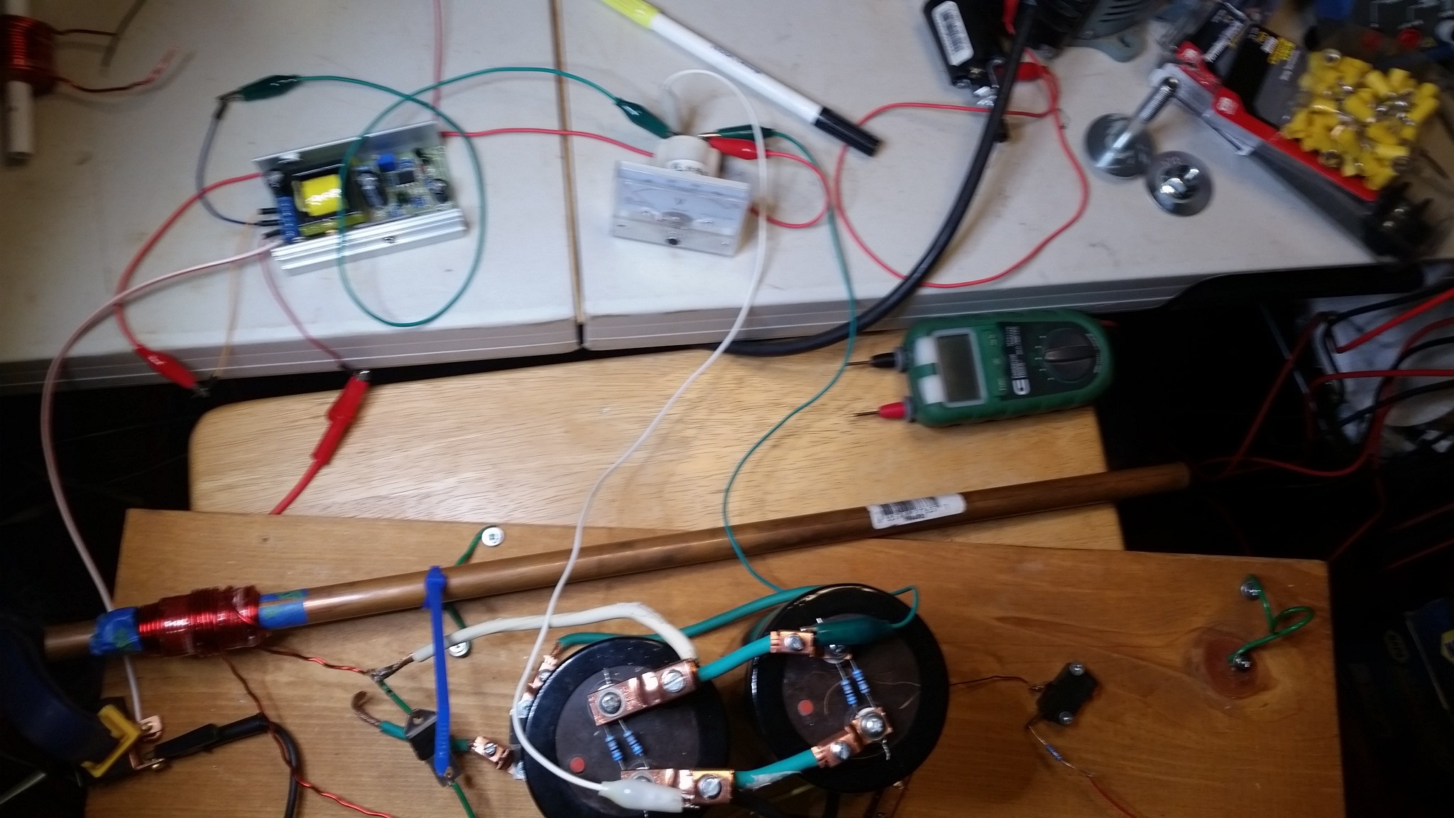
First thing I did was try to find out what Caps I could get. I ended up finding 450v 6800uF large electrolytic caps that are a little bigger than a soda can (pop can if you live in the NE USA) and seemed that I could get a decent amount. I ended with 5 which is intended for an eventual 3-4 stage CG. I sourced these through AliExpress out of China. -- Hmm I will have to note this some where more appropriate but - I live in Guam, a small island in the middle of the Pacific. 30 days for anything to ship. So any design change sets back everything a month or more. So I had 6 or 7 months of just research and design before I have even gotten to this point. this also lends to parts that are highly likely to work and not burn out under the specs.--

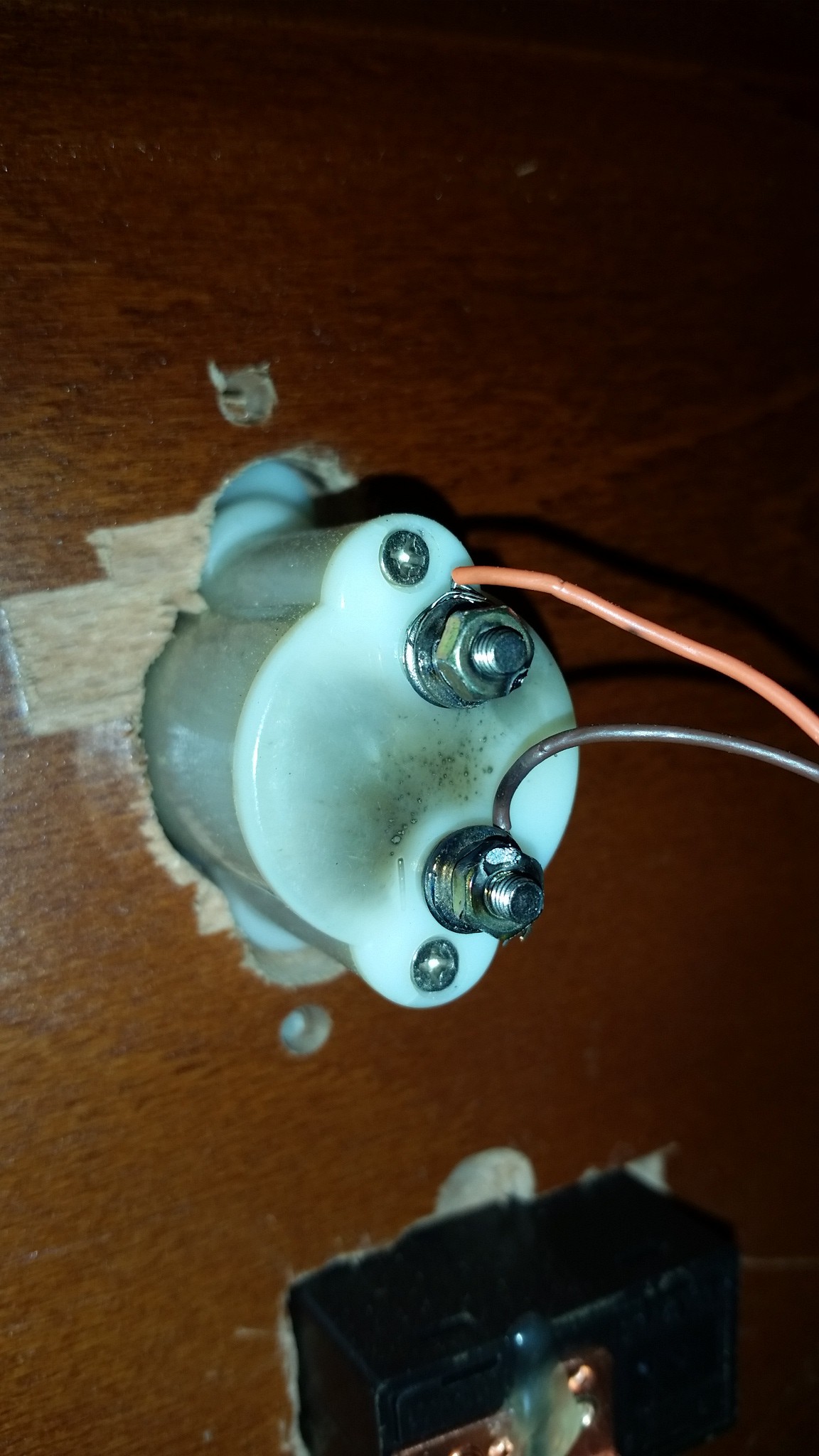
With those caps now we need to find a switch. Lots of choices, ( IGBT, Mosfets, SCR .etc) The ideal choices that can handle the 1200-1600A are Holy Sh!t expensive. The long and short unless you have some awesome connections and can score some awesome IGBTs you are going to be stuck with an SCR for your first switch. I chose the KP100A again out of china. The problem with SCRs is that they only open they don't close on command. so you can loose your hole charge but this can have detrimental effects on performance. IGBTs can switch off the flow so you can time how long your coil is magnetized. This SCR can be triggered open with a simple 18650 LiOn battery and with a Normally Open (NO) switch as the trigger.

Now the safety diode, which protects the capacitor, allows the energy in the coil to circulate until its dissipated as heat, basically. I chose the RURU15060 to handle High Voltage and Amperage. Again out of china.

So we have the Caps, the Switch, the protection diode, what about the
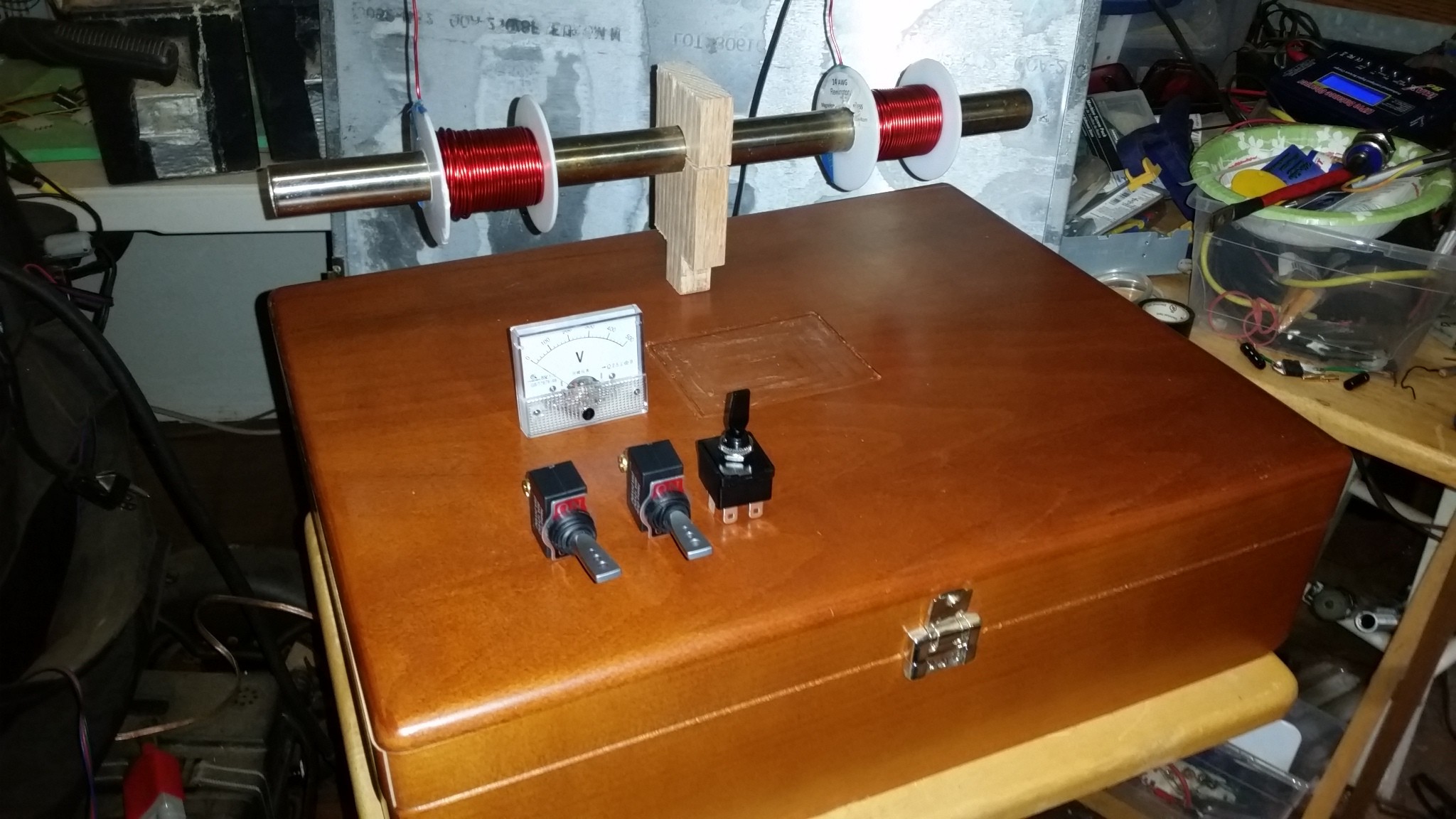
Coil?

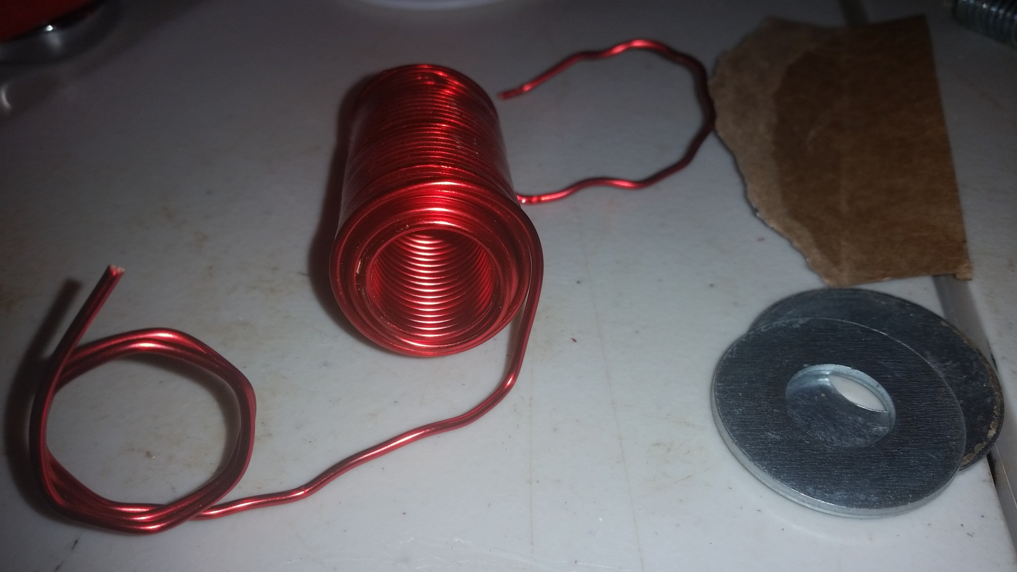
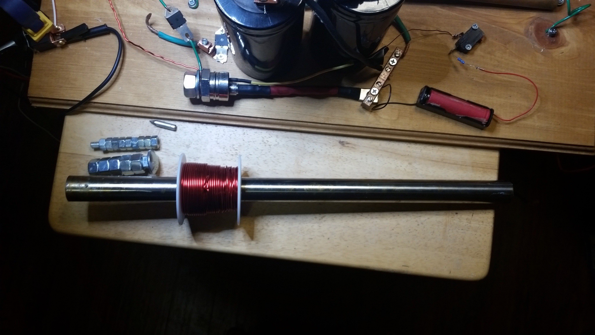
First Coil - After research I went with a 14awg 3 Layer 31 turns per layer. And a 31g bolt as a slug. I wrapped around a 1/2in (.5in) Copper Tube. This was specifically for proof of design. I changed it rather soon. It was quite interesting after firing it a dozen times or so I saw the looser ends of the coil get pulled to wrap around the center of the main coil. How cool. An empirical demonstration of how the coil constricts upon itself. These loose coils were the ones on the ends that did not get included in the epoxy coating. Using the 450v 6mF cap I get an under-saturated slug that limps across the room.

The second Coil - I wanted to use a plastic tube so I grabbed a round tube from a vertical blind, the rod that twists them open and closed. at a 10mm OD and 6.8MM ID it allowed for a nice small slug. I used a 10mm metric bolt that measured at 9.85mm diam. I epoxied large washers to the bolt and Nut to make a form for the coil. I need to add a layer of Tape to get me the last .2mm to allow the coil to transfer from the former to the plastic firing rod. This coil is 7 layers... Read more »

  • 4 × 450v 6800uF Capacitor Large Electrolytic Capacitor
  • 2 × KP100A SCR Silicone Controlled Rectifier AKA, a Thyristor. It's a HV Switch
  • 2 × RURU15060 Diode A High Amperage Diode used to protect the Capcitors.
  • 2 × 500V DC Volt Meters These gauges will show the voltage charge on the capacitor banks
  • 2 × 9v-450v Boost Converter used to charge the Capacitor banks from the 12v battery pack

View all 8 components

  • New Case Same Probs

    3dscuba10/12/2015 at 12:32 0 comments

    So its been a little bit since my last update but I have been working hard. Lots of things to overcome. I wished to show the end product but of course there is growth to be had and I must learn a bit more to make it all work. let me show you a series of update pictures and explain them. Quickly..

    showing the small bleed resistor and mounting of two caps in parallel.

    Beautiful new housing with the simple wiring needed without an Arduino.

    Showing how a laser can be powered in place.

    Shows the mounting of the small Jig needed to hold the laser and the LED to monitor the signal.

    Nice surface layout showing the two charger voltage meters with on/off switches, the two Thyristors (SCRs) with their safety switches each.

    The daunting task of trying to manage these wires all over!

    Initial close up

    After some nice wire wraps to help.

    Added some High Insulation rubber shields to cover the HV Caps.

    Here is where something shorted at a nice 250v ack ack farads of amps and shit I'm going to sit back and reassess my design.... turns out the voltage divider to monitor the charge circuits was attached to the negative vs the positive of the volt meter. oops/ damn :(

    The programing is coming along and is 95% there I will release when folks might actually help feedback on it. :)

  • The Next Build

    3dscuba08/30/2015 at 08:00 0 comments

    Ok, so I have found this beautiful display case that was for a fancy scuba regulator. I think it will make a nice Project Box. But I have some difficulties setting up my design. Here take a look.

    Notice the sizing of the switches and Voltmeter. I will use two wooden mounts like the one shown in the middle of the Tube.

    Plenty of space to place 4 caps as 2 banks, two 450v charges, the 12v battery pack, and maybe even an Arduino Uno if it comes to that. I plan on using that drill bit to make holes to mount the SCRs through in the Lid.

    Lots of real estate on the bottom side of the Lid. I will make two through holes for the mounting of the coils and tube. two more for the SCRs and then bunches of others to mount switches and maybe LEDs if I choose to use the Arduino.

    Sadly I had planned on a nice fancy wooden square mortise/tenon joint to hold the tube mounts but after several failures at drilling and chiseling out the wooden blocks.

    So, I have scrapped that idea and am going to glue it and then if needed make a pin to keep it in place.

    I am now in dilemma. I have been experimenting with IR sensors and emitters and found, at least in the ones I have, that the voltage rides high (5v) and then drops to 3.2v-3.8v depending on the intensity of the IR LED shown on it. When testing with photo diodes it is a big change in resistance that is measured. My initial thought was to directly trigger the SCR via a transistor or relay without using a processor in the middle. But just don't see an easy enough ( or any) way to do it. Introducing an Arduino type processor increases, not only options but complexity in a significant fashion. I have nice little red lasers that are easy enough for me to work with and the photo diode goes from something like 30k to less than 1k from Dark to Light. This would be very easy to process on an arduino but I am not sure about delays. Does a physical relay work fast enough in this scenario or do I have to figure it out with transistors? Once I have added the UNO I could then start to add fun little LEDs or incorporate speed calculations in to it. This may be the necessity in the long run no matter what, but I feel like I might be rushing things. Then of course there is the question of how to isolate the electronics from all the feedback from the coils. I'm not usually some caught up in the aesthetics of a project but I love the idea of lots of switches, meters and LEDs. I think I'm just slowly talking myself into it...

    Guess we will find out on the next post. Feel free to put your own two cents in.

  • Thunk!

    3dscuba08/13/2015 at 06:39 1 comment

    After Shaving down the head of the bolt to make it travel through the stainless steel tube, it weighed in at 148.8g WoW! I was a little worried I was going to big but what the hell.

    Ok, so I obviously wasn't thinking it through with the wiring of the trigger. FAIL. But it was just a dirty little setup to see if the projectile would even fire. It does pretty well too :) You may notice a few things here. One - I had a nice little blast shield in place in case the make shift setup proved its high likelihood of blowing up. and Two - the coil ripped off the back end of the tube! I still had a good deal of forward momentum on the projectile though.

    After this initial setup with all its ugly wires. I added some screws in front and behind the coil to hold it in place. I also placed an old dead battery on the platform to help hold it in place. I used a small Li-Ion battery pack (11.1v) to power the trigger this time. After reattaching the coil, the second shot is below.

    Curiously, there was enough of a back spike that the battery pack started to overheat. Hot enough that I put it in a SS container and put it outside. It never burst into flames though :( You probably noticed that the coil still shot backwards. So there is much more speed to harness here :)

    It appears to have arced from the coil to the nail during the second shot. As I said before I butchered the coils pretty badly when I was attempting to free the second lead initially. So, I will need to re-enamel some of the line and probably soak it in epoxy to hold the wire in place. But overall this feels like it has some good Umph packed in it. Now I just need to stop making these half assed setups and put together a little bit higher quality one. I need to look into the IR sensor setup as well. Until next time :)

  • Summer Progress

    3dscuba07/25/2015 at 06:15 0 comments

    We last updated with talk of a salvaged SS tube with an 1in OD and a prefab coil. Getting the leads of the prefab coil (the spool of wire) was a complete failure. I could not get to the interior wire of the coil without destroying the coil or plastic around which it is wound. After messing up two coils I decided to rewind one spool onto the empty spool I had with each lead exposed. I ended up with two half spools, both of impressive enough size. I think I am going to look into an IR LED triggering device. I have had two typhoons and a trip to Europe since my last post, so please forgive my slow progress as of late. I got the electric cart working well, and haven't checked it since the two typhoons (its stored outside) we will see. The LI-Ion battery has been working quite well, maintaining a good charge consistently. Not bad for salvaged batteries from old laptops. I received my second 450v charger to replace the one I thought had burnt out, so now I have two chargers.

    I must admit I fell silent for a bit when I realized I started speaking on the videos, and I wasn't sure how entertaining I am. I need to learn a little more about editing so as to keep the videos short enough and still interesting. The ones I babble away on go too long without much going on. Sorry, I will work on it. I have another trip to go on, so the updates will be a little slow.

    For now I want you all to know the project goes on, and I will be posting more as I can.

  • Fail, then Fail again

    3dscuba05/28/2015 at 15:02 0 comments

    Well, it's been a bit. We had a small (109mph) typhoon on island and I lost power and several segments of my fences. I am trying to get back on track, sooo

    ok, so trying to use the stock wound coils failed. I could not get to the interior wire without destroying the case and adjacent wire. I ended up deciding that I would have to rewind the whole thing on another spool. It kind of defeats the purpose. I will probably do this at some point but I was too frustrated. So I decided to make my portable power supply. I took some 24 18650 Li-on Batteries to make a 12v battery.

    I bought 24 single cell battery holders. Found an old Chivas container that would fit them. cut it all up and made it so I could mount 4 cells layered to make 6 layers of dual cells. It gives me a large 11.1v (12v) portable bank.

    My friend was leaving island last night so we grabbed the original coil and put it into the dual capacitor setup and launched some slugs :)

    after some sparks and destroyed boxes, we had smoke. bad smoke. I think I fried my capacitor charger. Everything overheated. Bad smoke :( but we had some fun on his last night. Time To Rebuild a Bit...

  • Revisited Original Coil Now with Twice the Umph

    3dscuba05/13/2015 at 09:56 0 comments

    So after adding the second Capacitor and seeing the underwhelming performance of a saturated slug. I though I might jerry-rig the original coil back up to see how a heavier slug might do.

    With the 33.7g slug we started getting a nice "thwack" and seeing some damage done to the box. Somehow I lost my original slug I had made for this coil, so I was also using some cluttered together nuts and bolt have something to shoot.

    After repeated firings I noticed I was getting some serious sparks cause by arcing between the coil wire and the diode wire on the SCR.

    After realigning the wires to make a more fluch connection with the SCR I no longer had sparks. You can see the carbon left from the sparks in this now flush photo.

    Seeing the improved performance I decided to up the mass to 60.5g. This was very successful. I had noticed on the 33.7g firings, the barrel would kick back and inch or so from recoil. So I figured with the added mass I would actually jerry-rig a remount to the wire harness on the setup. I figured it would give me more KE on the projectile. I also started putting a heavy Battery on the top of the box to help keep it in place and absorb more of the energy from the slug. The box is filled with packing beans and extra cardboard so I don't worry about it going through the whole thing.

    After Firing the 60.5g slug from the mounted barrel it was clear jerry-rigging was not going to work. The barrel was ripped from the wire harness due to the large recoil generated.

    It is obvious that this original layout, that was only to test the concept, is no longer adequate and a redesign of the layout is needed. That will be the next step. I also need to move the trigger further away. It's getting a little scary huddled over this as I flip switches and triggers. Might as well start looking for the long term design. I have one last shot I would like to try, Maybe.

    Sooo, I was wondering around at the bottom of the ocean ( live on a small island remember) and I found this great Stainless Steel Tube at 125 feet. Salvage! It's a 1 inch OD and .889 inch ID it also fits perfectly inside the spools of wire I order in from china. So I figure I might as well see what happens when I put a prewound, from the manufacturer, 'coil' around the tube and put a Big Fat Slug in the chamber. The Max mass of the slug is 150.6g and I need to grind the head down to fit in the barrel. It will probaby just plop but I have to try :) I'm a little worried this might be out of the specs for my current parts so I need to do some math, mainly because I think I will want to put a third cap in to push this fat thing. Getting a little concerned about eddy currents too. We'll see.

    One last thing. When talking about long term design. I acquired a fun little piece of equipment. It is one of those electric shopping carts people ride around Home Depot and K-Mart in. :) I have gotten it all wired up and now, short of maybe chaning out one potentiometer that is slightly miscalibrated, it works. The nice part is the mount where the basket went is perfect for a nice sized Coil Gun :) Yea Mobile Platform. It just makes the brain hurt with potential :) I will get a picture of it when I have some daylight.

View all 6 project logs

Enjoy this project?

Share

Discussions

3dscuba wrote 10/30/2015 at 07:35 point

I bought these cheap little boost converters and built a 12v Li-Ion battery pack. for 17 bucks with free shipping. It takes 21 days to get here and you need to be careful about burning them up but they work like a charm. Link below:

  Are you sure? yes | no

Mihir wrote 10/30/2015 at 06:27 point

Hi! Been following your project and wanted to ask a couple of question. I've built my own coil gun with a cap bank of 12x 400V 350uF capacitors in parallel. I charged it with a lab electrophoresis power supply which was super expensive and barely effective. 

I've been since looking for a simple, effective way to charge high voltage caps effectively. So how did you manage to do it? I've been thinking an easy way out would be to wire several camera flash chargers (8 to 10) in parrallel to achieve high charge rates, and power it off a single battery or easy to build power supply. 

Please do let me know, I'm very curious to hear. Keep up the great work!

  Are you sure? yes | no

Similar Projects

Does this project spark your interest?

Become a member to follow this project and never miss any updates