 jaromir.sukuba
Making GSM phone utilizing GSM modules is not that complicated. One needs to use MCU with UART and few IO lines and then truckload of patience for writing decent parser of AT commands - that can be nightmare to do correctly. For this construction, I used extremly simple one, with no errors checking.
Let's consider two keys, one rotary dial and one display as complete user interface for this phone, plus serial line to GSM module. This would need approximately 12-16 pins of MCU. Because LPC810 has only 6 GPIO pins, I needed to do it in different way. For this purpose I used 74HC164 shift register.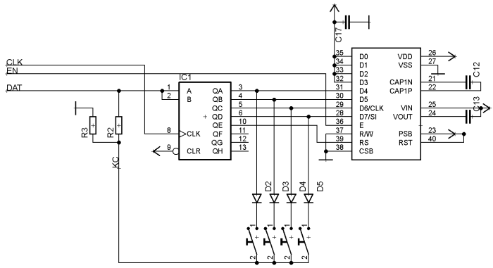
Now, we can control 4 buttons and one display with 3 IO lines.
For controlling display, we need to shift out 5 bits (data line + RS) and then pulse EN line, assuming display works in 4-bit mode.
Reading switch state, let's say te first one, we need to shift out word 0x01, then switch DAT line from output to input and read its state. When swich is pressed, DAT line goes high, or is puuled down by resistor R3 otherwise. For reading other switches we need to apply this process for words 0x02, 0x04 and 0x08. Display data lines will change state during button check, but while EN is low it doesn't care.
R2 value needs to be selected so that MCU output will override logical value from buttons, something like few kOhm will do the job. R3 is only pull-down, 22kOhm seems like good value. Diodes are needed to avoid short circuit between shiftregister outputs when more than one button is presssed.
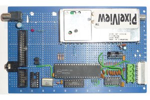
Adding MCU (LPC810 in this case) and GSM is simple. Everything is powered from voltage regulator switched from STATUS pin of GSM module. When user powers on the module with button on PWR pin, STATUS goes high. It is high until GSM module is powered off by user intervention or automatically.
Code in MCU works in two state machines - one is in interrupt handler of UART Rx line and captures incoming characters into buffer and sets particular flag when buffer is filled with particular AT sentence.
State machine in main loop checks for those flags and changes state with respect to those flags or user buttons. This machine works in cca 16ms cycles - and this is period of scanning the digital inputs, including rotary dial contacts.
Device is plaed into plastic box. I selected quite huge box, because rotary dial itself is huge. On the other hand, this gives me a lot of room for minor tweaks needed for quick design. I used 1000mAh Li-Ion cell, but bigger would allow for longer stabnd-by tim
TODO
There is a few things missing. Remaining capacity of MCU FLASH and current PCB layout would allow toggling DTR line and introducing power-saving modes for extending stand-by time. Easy should be also using CLIP function to display telephone number of calling person.
Take look at picassa photoalbum
https://picasaweb.google.com/111890741167251011072/RotaryDialMobilePhone


 Keith
Keith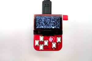
 deʃhipu
 Lauri Pirttiaho
 John Lonergan
You really ought to make a video of you using this in public :)