 SwiftyTheFox001
Relay Logic is neither something new or very complicated on this scale and a rather similar project from Dave Gönner is also already online (even though never completed), so why bother?!
Simple answer:
I wanted one for myself and the project lets me optimize my multi-PCB workflow that I will reuse for another relay-less project. So in the end I will not need to develop an extra prototype PCB. It was also the first time I ordered from a well known Chinese PCB supplier that I wanted to try out before I throw more money at it.
I hope you like my realization of the relay clock. Files will be put online soon, so please be patient. At the moment I am already soldering the first PCBs together, so this should be done soon.


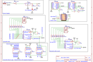
 Since I planned to order a minimum of PCB designs (price!), I needed to develop even the modules modular, mostly via jumper pads that could be soldered together when needed. I also got rid of the Routing-PCBs and reduced the Signals to a minium.


 Mario Gianota
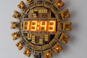
 Dave Gönner
 rawe
rawe
 Yann Guidon / YGDES
They are way to bright :) ==> They are way too bright :)