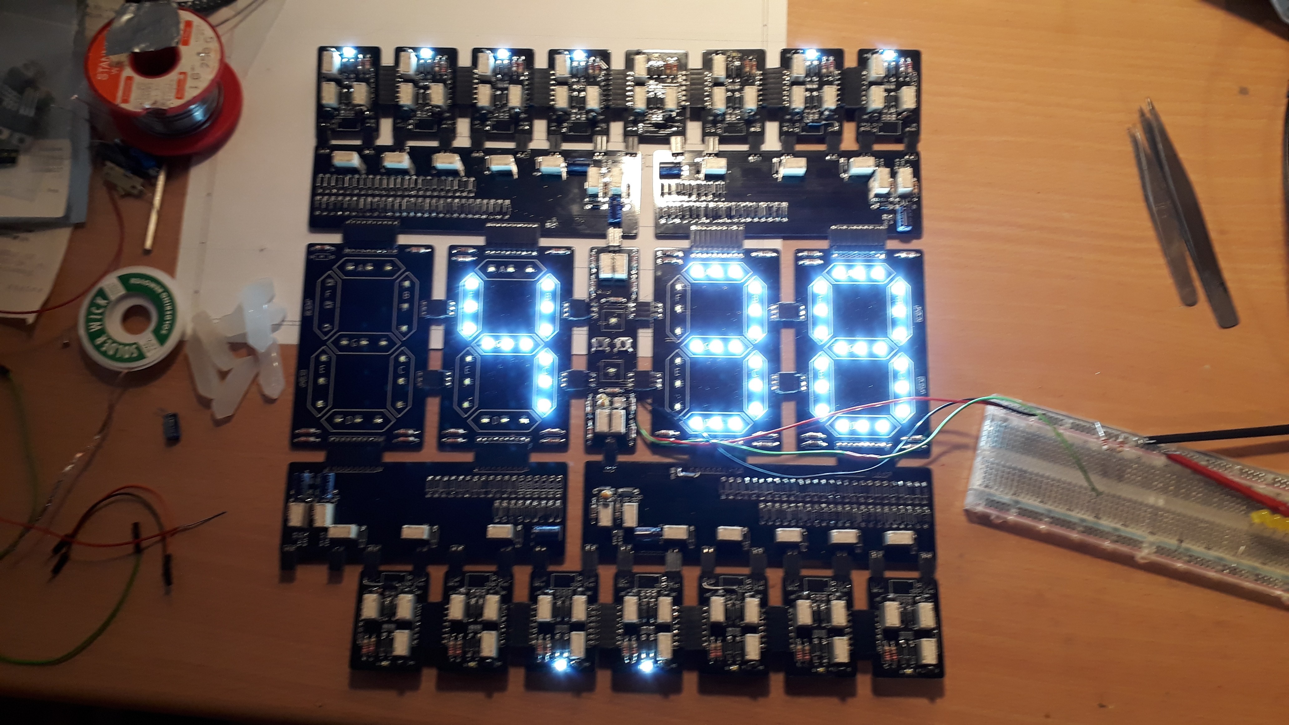
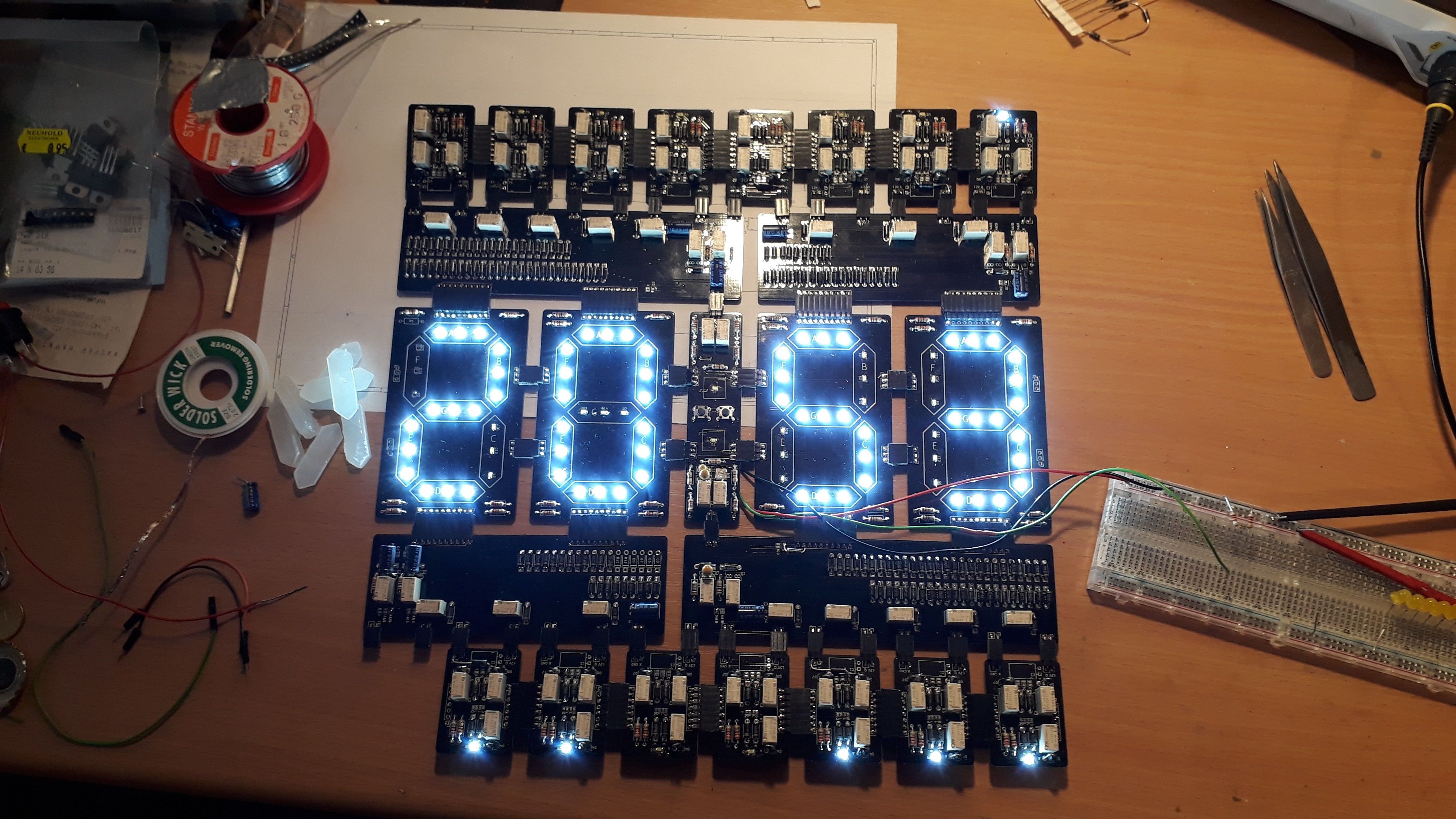
Last Friday my last PCB package with the updated "dots" section and slightly modified "digits" finally arrived.
After some bug fixing the whole clock worked flawless when clocked with the built in buttons. The MOSFET drivers with the relays for switching functions (RESET, CLK1&2, ADJ) via an external source work fine as well. Bigger MOSFETs could have replaced the Relays in general on this sections, but this was not the intended way of this project, wasn't it? :)
The thing that cost me most time was the LM1117 ADJ - it seems that I have chosen too large resistances because the curve was so much off, that I was more successful by trying out some combinations instead of calculating it. Yes, I was designing it at first with 1,25V between the adj pin and gnd, but the newly calculated resistor values should have been working.
Here are some pictures:


A video is following up once my clock source is operational and the diffusors are in place. You can see the diffusors already lying right next to the clock, they are looking promising with the lower ADJ voltage set. The full 12V are a bit too bright... Maybe I'll change the resistances once more before I put the clock on the wall.
 SwiftyTheFox001
Discussions
Become a Hackaday.io Member
Create an account to leave a comment. Already have an account? Log In.