Current Consumption
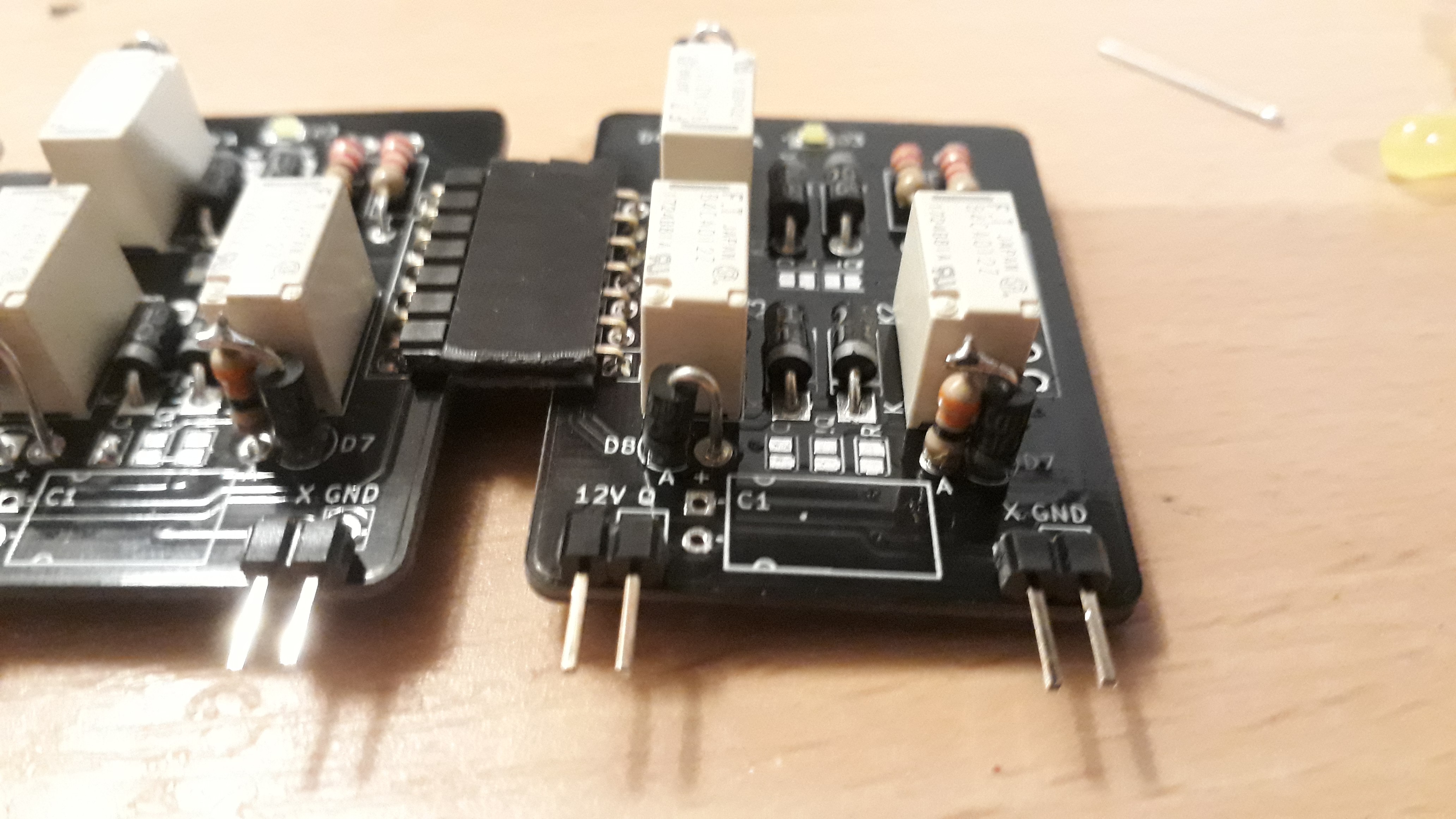
During soldering together and testing the first FF's I got the idea to reduce the current consumption of the whole clock AND to keep the LED's on the FF's. The LEDs I use are still damn bright when used at 1/5th of Ifmax, so the easy fix was to increase the serial resistor to 2k2. The thing that bothered me more was the reset current. The current during reset is only limited by a 220R Resistor and a Diode - so roughly 50mA@12V. Multiply this with 15 (all FF's) and we get a whooping current consumption of 750mA - just for the reset pulse. A serial resistor between the 220R and the Diode D7 (Reset) would reduce this. The limiting factor here is the reset Voltage of the Relays: 1.2V. I also found a beautiful way to retrofit them on the FF's - I just mounted them next to the vertical Diode D7:

I went with 100R first, setting the reset Voltage to 4.16V@35mA, but Some Relays did not reset properly - like it is written in the spec. So some Relays got 33R instead. This means that I am not getting the way better reset current of 525mA thanks to some relays, but it is for sure better than what I had before. If I encounter problems due to a too high voltage drop over the reset line, I'll just reduce the resistor again for the problematic relays.
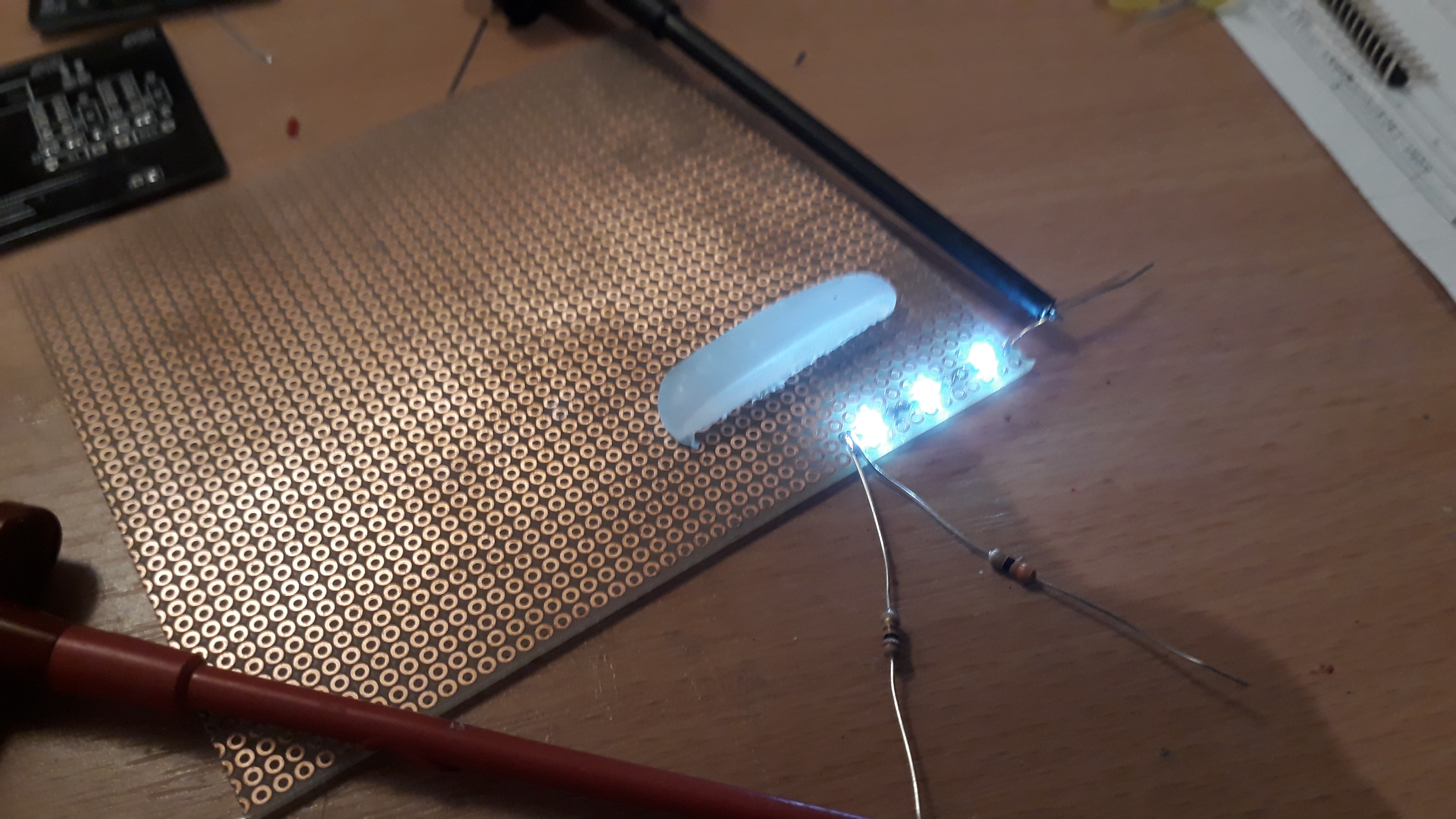
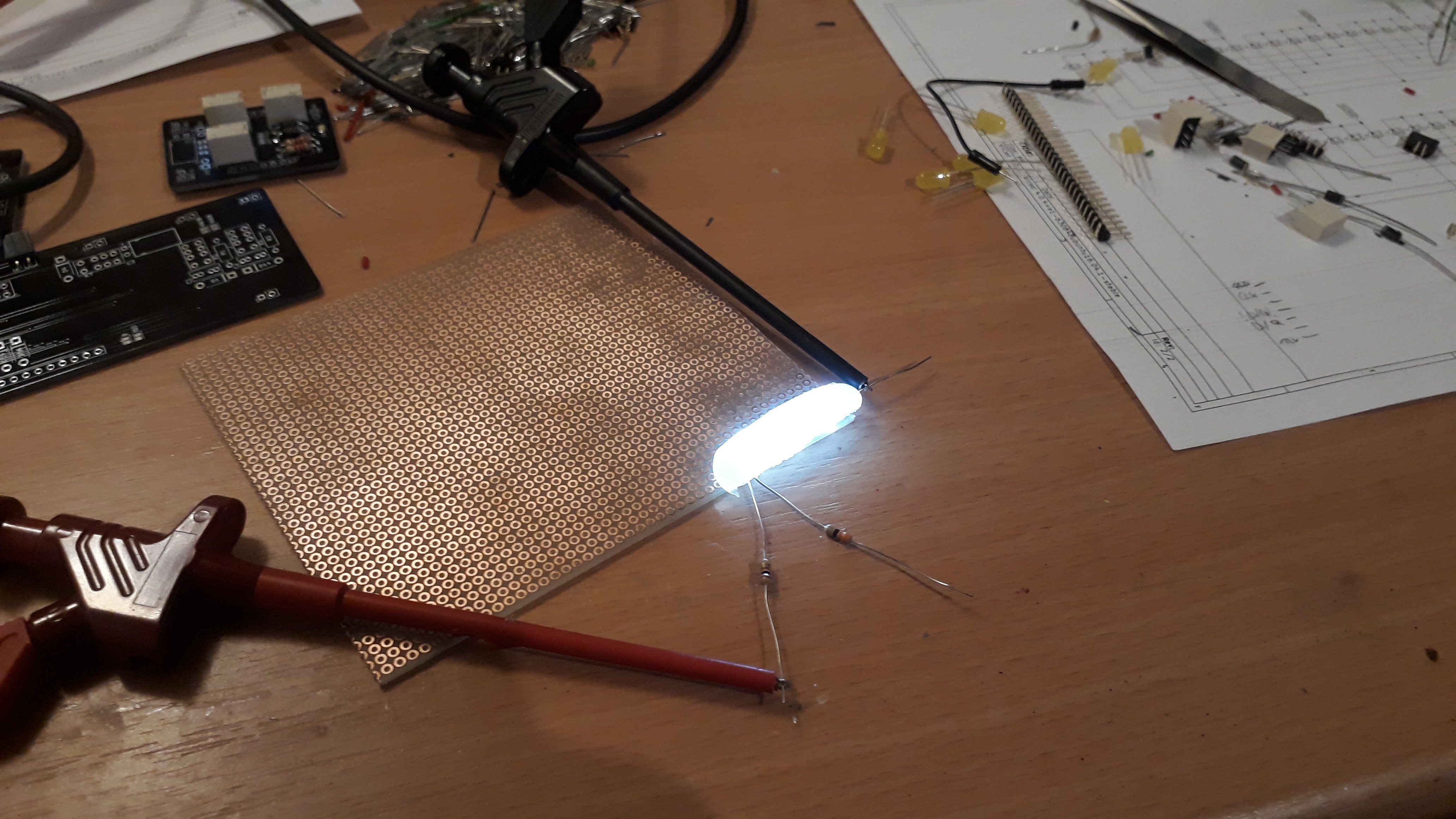
I also played around with the dummy hot glue diffusor I made. Reducing the current to the half does not change anything here as well and is still readable during daylight.


The sum of these changes will reduce the electricity cost for this clock now from approx. 7€ down to 3,5€ per year - Totally worth it :P
Bugs & Fixes
I designed the PCB's with the mindset that the Circuits might need some updates (e.g. C1 and the A!&B logic output option for both Decoders, the cap to stabilize Supply on every FF), but of course one cannot plan for any mistakes in my schematics.
The minor and easily fixed bugs were two floating nets on DecoderB that should be connected to GND and 12V. A very short bridge was all that was needed.
The more embarrassing bug was the return / loop signal for the counters. I designed in some solder able jumpers to easily "wire" these on the FF's, but only for ONE line: Q->D. After adding the missing second signal !Q->!D, I realized that I totally failed again: The correct wiring would be Q->!D and !Q->D for the loop lines. *facepalm* So I added / hid two wires for these signals on the back of every decoder.
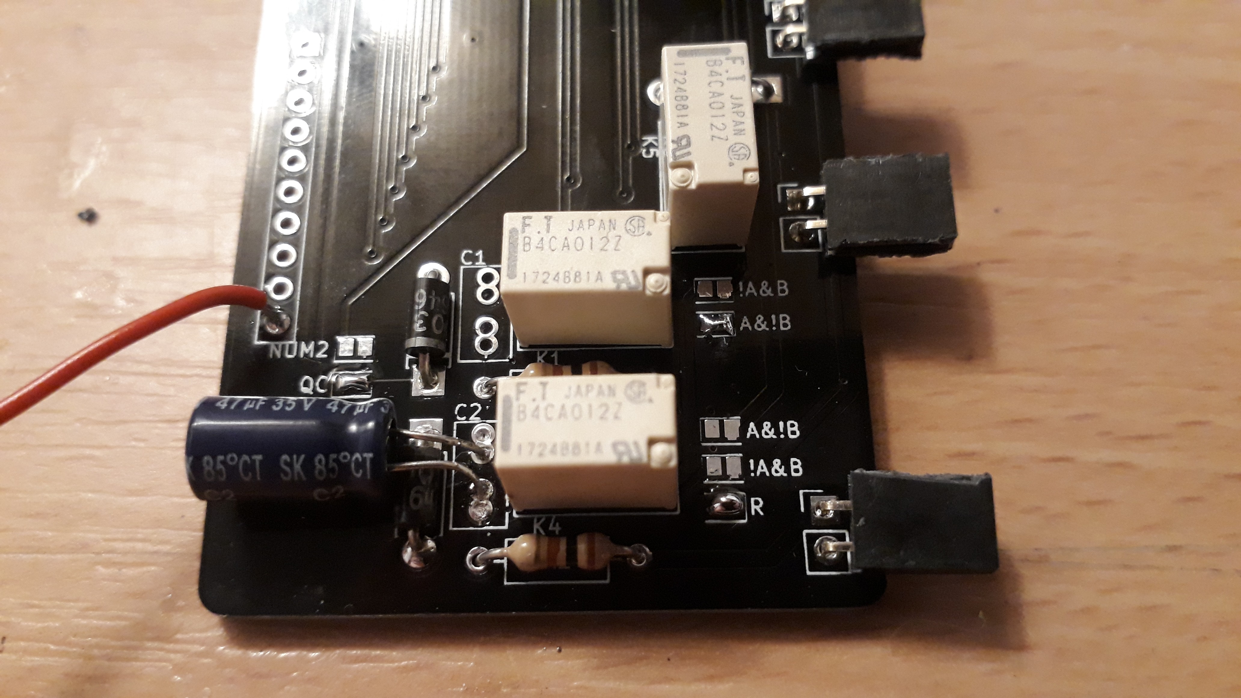
Some minor miscalculation was the delay-cap of the Clock-Pulse Logic. 10uF was not sufficient to trigger all FFs - the pulse was too short. So I took one of the 47u Elkos that I had for this project, but unfortunately I designed only a footprint for tantal caps... Looks a bit ugly and misplaced, but hey, it works!

The changes will be implemented soon into v1.1 of these PCB's on github. Not that I expect that someone will ever use these schematics, but I hate to keep a bug alive out there in the wild...
 SwiftyTheFox001
Discussions
Become a Hackaday.io Member
Create an account to leave a comment. Already have an account? Log In.