 Paul Kocyla
OVERVIEW
-------------------------------------------------------------------------------------------
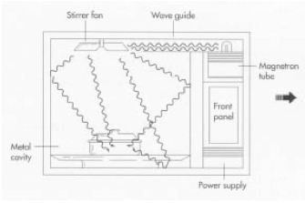
The EMdrive is derived from a closed cylindrical microwave waveguide. The main difference is that one end is larger than the other. When RF is fed into the cavity and a resonance is achieved - according to Shawyer a thrust force will occur.
---
The first builds have not been summarized due to documentation cleanup process
---
EMDrive V3
===============================================
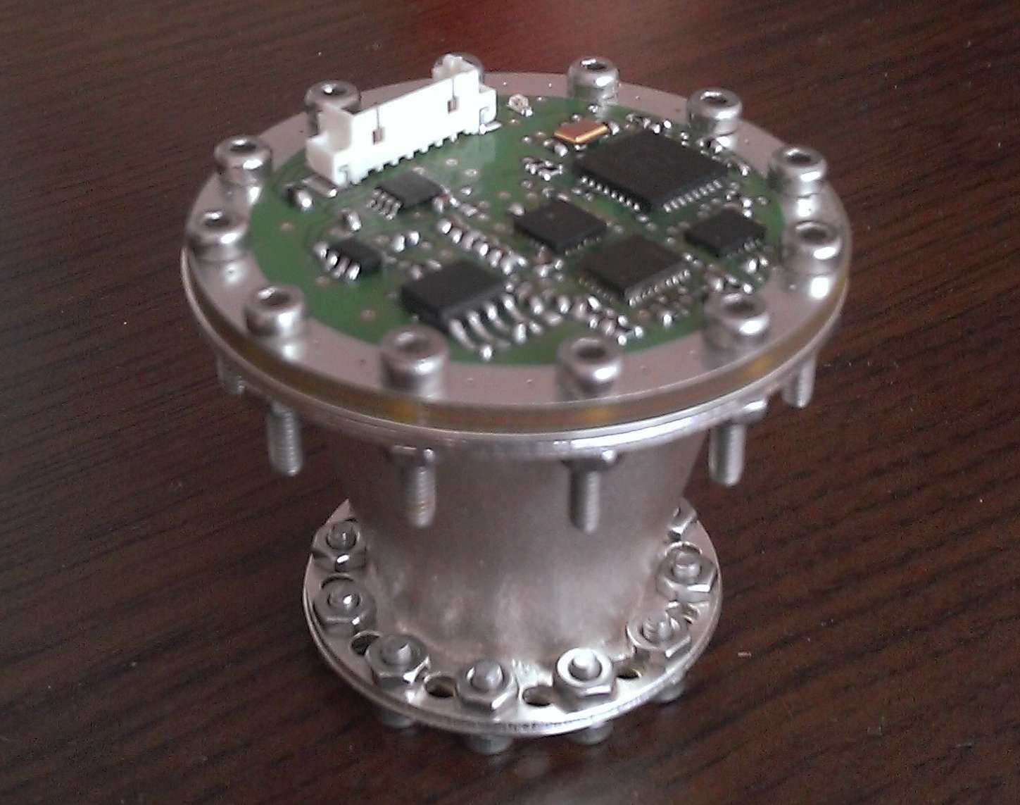
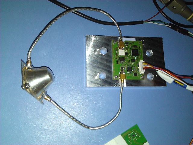
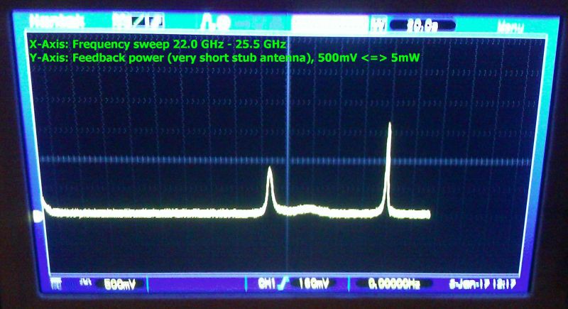
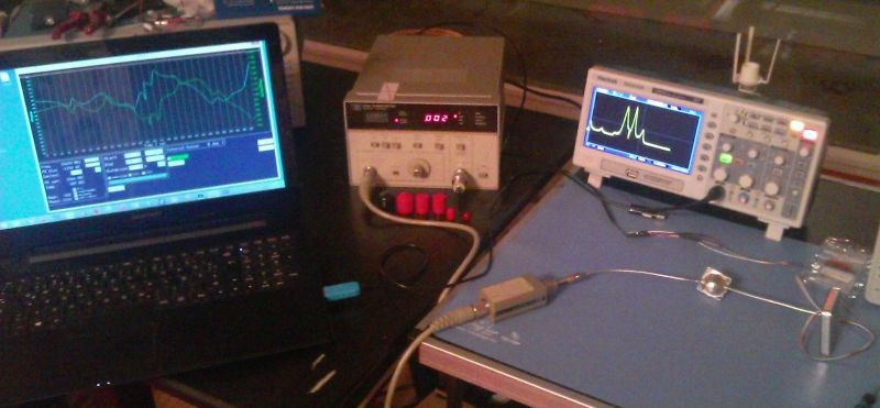
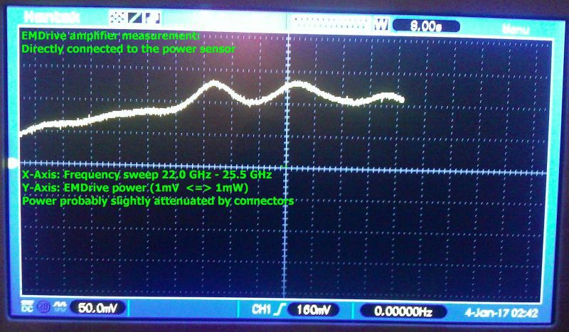
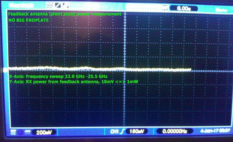
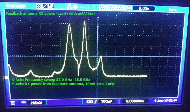
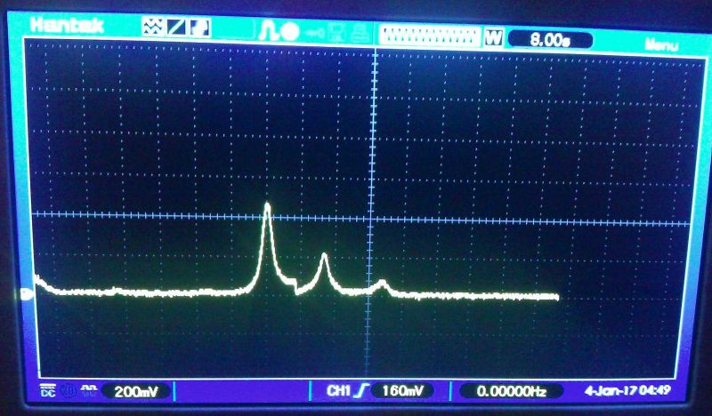
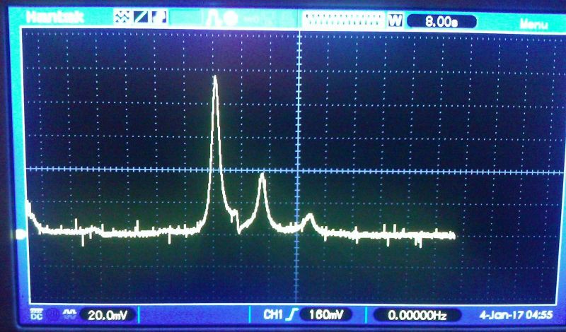
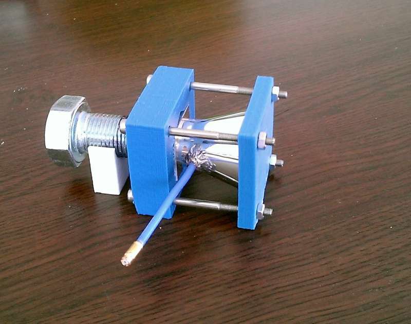
The V3 is a silver cavity build, fed by a fully controllable RF source capable of beeing tuned between 22 and 26 GHz.
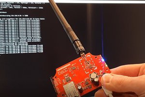
The reflected power can be measured in amplitude and phase.
First measurements with acoustic vibrations (by OOK modulation of the RF source) show a force near the designed target resonance frequency. The last experiment is reproducible and shows clear signals. Further tests must be performed to check for directivity of the force.
PS: Many many thanx to all the people who gave us very helpful hints how to improve the system. It has been an exciting ride for us until now, and we hope to provide a functional Baby-EMdrive soon
Special thanx go to TheTravellerEMD, Marvin Macportain, Keegan Reilly, Aurelio Chargb Ramos
EMDrive V4
===============================================
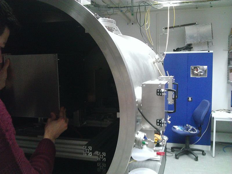
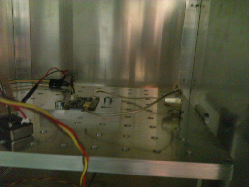
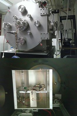
This build was a complete integrated version which has been tested at the TU Dresden with Prof. Tajmar.

It should have been the flight version for our satellite in case the test would heve been more successful.
We had thermal issues during testing, with temperatures of the amplifier rising up to 90°C.
This led to a massive power derating in the amp.
We had to reduce power to keep the temperature low, so the final force was only slightly above the scale´s resolution.
Other effect like lorentz forces and thermal deformation had a significant pattern in the measure plot.
Tests have been made for 0°, 180° and 90°
Results are not for publilcation yet - we will perform further tests with version 5.
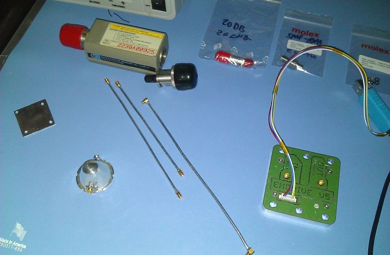
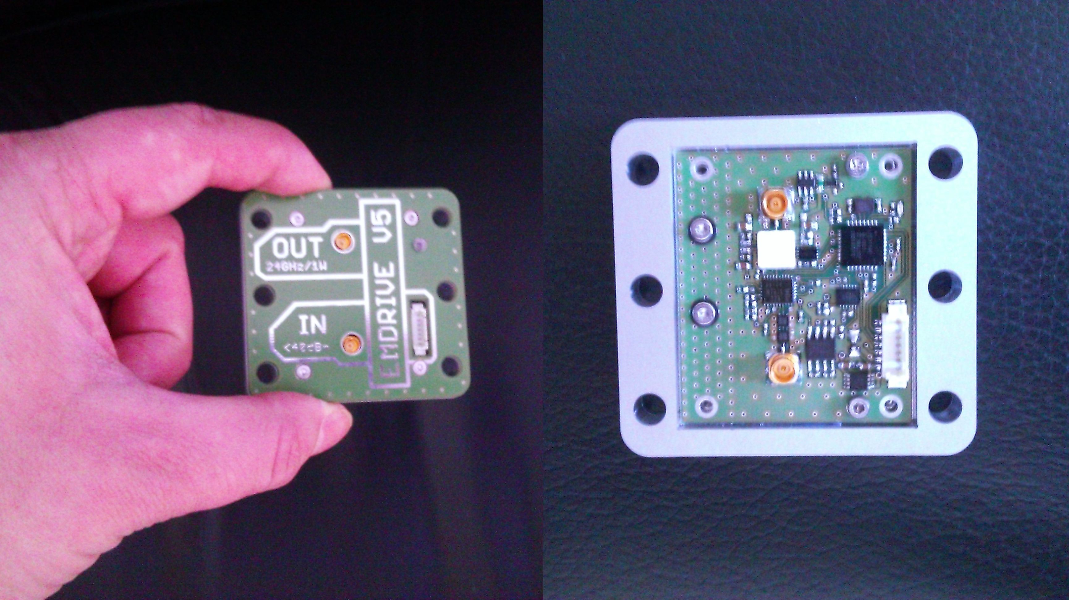
EMDrive V5
===============================================
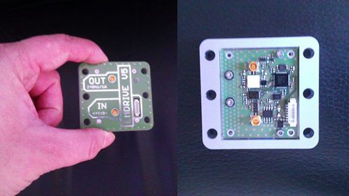
This is a development unit - derived from the V4 - which is intended to be tested at TU Dresden. It has some improvements to solve the problems that we had during testing of the V4.
It has an amplifier with better efficiency and is well thermally coupled to the casing for better heat management.
The new silver cavity geometry has an improved shape based on a proposal in Shawyer´s actual patent paper.
This shape will ensure that the pathlengths of the reflected waves on the longitudinal axis of the cavity is always kept to a multiple of lambda/2 of the resonance frequency.
 I am not allowed to publish detailed results, but some information upfront:


 Patrick Van Oosterwijck
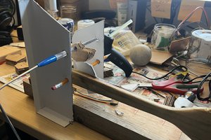
 Hugh Brown (Saint Aardvark the Carpeted)
 Brook Patten
It's so cool to see people that are much smarter than me running serious experiments on things that seem to violate the law of conservation of momentum, it shows that people are willing to try new ideas.