 Paul Kocyla
Designed a second print for experimenting with 3D printed materials.
It´s just the raw cavity made of polished stirling silver, printed in high resolution.
It´s a good material for waveguides.
I´ll make the outer frame of 3D printed ABS plastic with a local printer - I should have got this idea before using the vouchers (price is the same after reducing the material volume), but hey that´s life. Let´s see what results we can get.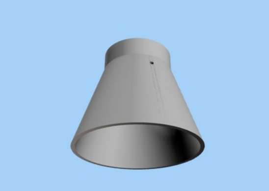
Discussions
Become a Hackaday.io Member
Create an account to leave a comment. Already have an account? Log In.
Hi Movax,
What are the new frustum dimensions with min and max length (end plate separation), spherical or flat end plates and frequency. Will then run an analysis with 16 modes to find any resonance.
All the best,
TT
Are you sure? yes | no
Height without the cylindrical endpart: 21.87mm
Height of cylindrical endpart: 5mm
Diameter small end: 16.12mm
Diameter big end: 29.64mm
Frequency is tuneable within 23 to 25 GHz (maybe more, but then the generator works out of spec)
The small end wall will be movable within the cylindrical endpart by a servo for automatic testing.
The endplates are flat - but a sphrical mod is also possible, because the cavity ends are open so we can flange different endplates to it.
Many thanx for your analysis, it´s really amazing that you´re doing that for us.
Do you also need the antenna position/antenna length, or does it not matter?
The current board uses a 3/4 lambda of 24.125GHz
The antenna hole is 5.55mm below the cylindrical endpart.
If this is wrong, we can make another drill. Unfortunately I could not find much information about the antenna position in EMdrives, just the standard 1/4lambda distance from the wall for usual waveguides.
Cheers,
movax
Are you sure? yes | no
That really is tiny!
Are you sure? yes | no
Could fit into a 2U-pocketqube. The advantage of a small EMdrive would be the testing on a load cell in a vacuum bell powered solely by batteries.
We are working on a load cell setup, and we have a suitable vacuum system as well. So step by step we hope to get closer to a good result.
Are you sure? yes | no
If I don't make any mistake, between 24 and 25 GHz your cavity may found resonance in several modes very closely, for the same big-to-small distance (TE013, TE114 and TM113). Don't know if overlapping modes are a good thing or not.
Are you sure? yes | no
Thanks a lot for checking the modes.
This sounds good and leaves room for hope.
I hope I can electronically detect a resonance condition while tuning the cavity. Unfortunately I didn´t find out how the power amplifier behaves with changing system impedance. If the power consumption changes significantly, our board will be able to detect it and correct the frequency output to maintain resonance.
Are you sure? yes | no
What will be the power in watts fed into this cavity?
Are you sure? yes | no
Theoretical best case would be 500mW, but I think there will be quite a loss due to improper matching, so I assume that maximum half of that will arrive in the cavity.
I planned two versions: One with a movable antenna and one with fixed coax feed. The movable one is printed of steel, so it has to be machined smooth and plated from the inside. We´ll focus on the silver cavity first.
Are you sure? yes | no
What did it cost to print? How thin can you make the walls?
Are you sure? yes | no
90€ with 1mm wall
Are you sure? yes | no