 Paul Kocyla
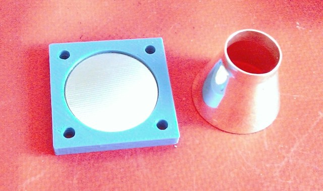
The cavity arrived from Shapeways.
The resolution is great. I will polish it from inside to make it smoother, although it´s already incredibly smooth for a print.
The big endplate is just a PCB - no work at all, just a circle in dimension+top layer.
A project log for EMDrive/satellite
Developing a small fuelless microwave thruster
The cavity arrived from Shapeways.
The resolution is great. I will polish it from inside to make it smoother, although it´s already incredibly smooth for a print.
The big endplate is just a PCB - no work at all, just a circle in dimension+top layer.
Discussions
Become a Hackaday.io Member
Create an account to leave a comment. Already have an account? Log In.
Yes the smoothness seems so incredible for a print! Any chance you can find a macro lens for iPhone or standard digital camera and shot some close-ups?
You should definitely use spherical end plates with your solid-state RF amp. Otherwise with flat ends you'll find resonance either in a very small area in the middle of the end plates, or on their periphery. But not both at the same time, which will decrease any -already tiny- produced force.
Flat end plates are OK when you use a noisy magnetron (with a much bigger frustum at 10x your frequency) because the magnetron has a large bandwidth and the discrepancy between the resonant frequency at the center and at edge of the flat ends of a frustum makes the most of that large bandwidth and possible frequency drifts.
With a solid state RF amp like yours, producing a precise narrow frequency, spherical end plates are warmly recommended to take advantage of all that small volume :)
Questions:
1/ Do you have a particular mode you'd want to excite?
2/ What is the shape and the length of your antenna?
3/ How do you know when the frustum achieves a proper resonant mode while tuning the small end inside the cylindrical neck? Will you use a VNA and measure VSWR and unloaded Q via S11 return loss?
Are you sure? yes | no
Thanx. I´ll make some designs for spherical endplates for printing in the next experiment runs.
Answers:
1) We want to permutate all possible parameters of the EMdrive, which means many positions of the small endplate and a wide frequency spectrum 23-25 GHz. The tests will be run automatically. So there is no specific mode planned
2) It´s a 1/4 lambda stub of 24GHz
Question: Is another length/shape better?
How about the antenna position?
3) The new board has a 40dB attenuated input, which could be eventually used as feedback.
I also included a precise power consumption measuring unit on the board. Unfortunately I don´t know how the power dissipation of the PA changes according to VSWR (could not find any info in the datasheet)
Are you sure? yes | no
To answer your question about the antenna, I imagine it looks like in this picture:
but smaller of course. To excite TE mode a loop antenna or a dipole antenna would be preferable, but these modes are harder to excite than TM modes. Yet TE modes seem to produce greater thrust.
It has been suggested over NSF by Dr Rodal that the best place to put the antenna would be near the big end, not near the small end. But this hypothesis is very recent so your build was maybe already on its way from Shapeways. If you had the chance to test the exact same cavity but with the antenna put near the big end, it would be the first time someone could show two different data sets from real-world experiments (and not only simulations in MEEP software). But first let's see what this new baby silver surfer is capable of :)
Are you sure? yes | no
Thanx for the answers. The silver cavity has a 1mm hole near the small diameter to put the coax in - maybe it needs to be drilled bigger.
If the thrust difference is a factor of 2-3, then we still would be able to measure it.
The first step is to get a clear measurement. Then we´ll start to optimize. We could close the first hole and drill another near the big diameter.
Are you sure? yes | no