Close
0%
0%

RaspiZero Motion Activated NOIR camera board

An RPi Zero-sized hat board with a Passive Infrared sensor, ambient light sensor and hi-power Infrared LED for lighting up a NOIR Camera

Similar projects worth following
This hat board is roughly the form-factor of a Raspberry Pi Zero and features a PIR sensor with amplifier, the output of which is compared against a threshold. If the signal crosses the threshold it sends a pulse to the Pi. A Python script on the Pi can monitor this signal and, when tripped, will enable the power LED and take a picture or video, depending on the code. Afterwards the picture/video can be sent via email or SSH/SCP for viewing.

The LED Enable line biases a comparator circuit where the output of an Light Dependent Resistor (LDR) is compared against an adjustable threshold. If the LDR voltage crosses the threshold, the LED will turn on to illuminate the subject. Otherwise, the pic/video will be taken with ambient light.

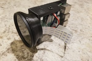
One of the challenges with this circuit comes from the fact that the output of the PIR sensor is VERY small (uVolts) and so it requires significant gain to establish a detectable signal.  Mounting a hi-gain circuit within centimeters of the PI Zero's WIFI antenna caused a lot of false positives due to the PIR circuit picking up noise every time the WIFI transmits.  

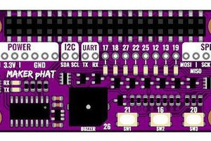
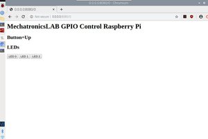
The solution I used here was to disable the WIFI in software while monitoring the PIR.  If motion is detected the Pi will enable the WIFI, send out the file via SCP or email, then disable the WIFI and go back to 'listening mode'.  If a user needs to get into the Pi via SSH, pressing either one of the buttons on the side of the box will bail out of the Python script and let the user get access.  Pressing both buttons will cause the Pi to execute a 'sudo halt' command so that power can be removed without risking corrupting the SD card.

sch - 1.01 MB - 02/18/2018 at 16:05

Download

brd - 180.22 kB - 02/18/2018 at 16:05

Download

Adobe Portable Document Format - 27.81 kB - 02/18/2018 at 16:05

Preview
Download

  • Circuit Description

    roger_archibald02/18/2018 at 16:36 0 comments

    PIR Amplifier/Discriminator Circuit:

    The PIR sensor is powered up via the Pi's 3.3V supply through a 10k resistor and bypassed by 10.1uF.  The output of the PIR is amplified and band-pass filtered by IC1A and IC1D, with potentiometer R14 allowing adjustment of the gain of IC1D.  The positive input of IC1D sets the DC output level of IC1D at 1.65V thanks to the resistor divider of R6-R9.  IC1C and IC1B are comparators whose outputs will go low if the output of IC1D crosses their thresholds of 1.65V +/- ~457mV.   When no signal is present, the outputs of IC1B/IC1C will both be HIGH, which will make the output of NAND gate IC2 LOW.  If the output of IC1D changes by > ~457mV, it will cause one of the inputs to IC2 to go LOW, resulting in the output of IC2 gong hi.  This output is routed to the GPIO header so the Pi can detect this motion.  If Jumper SJ1 is closed, LED1 will turn on whenever motion is detected.

    Ambient Light Detection Circuit:

    IC4 is a Comparator that's used to detect ambient light and determine whether or not the Hi-Power LED is necessary to record an image/video.  Just prior to recording, the Pi will make the 'LED_EN' line go HIGH which will bias the resistor divider made up of R16/PH1.  PH1 is a Light Dependent Resistor (LDR) and its resistance is inversely proportional to the light on its face....The darker it gets, the higher the LDR's resistance and so the higher the voltage on the positive input of IC4.  The negative input of IC4 is tied to a resistor divider made up of R15, R19 and R24.  R19 can be adjusted to set the threshold for the comparator, essentially determining how dark it has to be before the output of IC4 goes hi.  R22 provides a bit of hysteresis to the comparator so it will not be 'chattering' if the voltage on the positive input is near the threshold.

    The output of IC4 is fed through a 1k resistor to 'LED_VSET'.  LED_VSET is used both to enable U2 as described below and is also fed back into the Pi so it can know whether or not it was dark enough to trip the comparator.  Currently the Python script on the Pi will append a 'D' for 'Dark' to the end of any filenames created when LED_VSET is HIGH.

    Power LED Driver:

    SAFETY FIRST! Note that the light generated by an Infrared LED is invisible to the naked eye but it is very powerful and could possibly damage your eyesight.  Don't stare at this LED while it's on, any more than you would stare at any powerful light source.  When active, the LED will give off a faint red glow.  If you see the glow, the LED is giving off potential harmful Infrared light!

    U2 is a Diodes Incorporated AL8861 power LED driver.  This buck converter uses the same 5V that powers the Pi to generate the LED supply.  The LED current is set via R13, and L1/D3 make up the rest of the buck.  C11 and C12 minimize switching noise getting back onto the Pi's 5V.

    Additional Circuitry:

    LED2 is connected to the Pi's 3.3V output via jumper SJ2.  When the jumper is shorted, LED2 will be on whenever the Pi is powered up.  LED3 and LED4 are tied to GPIO's and can be controlled by the Python script that controls operation.

    Buttons Switch1 and Switch2 are tied to GPIO's and allow the user to interrupt the Python script running on the Pi.  This can be useful since the Pi may be sitting there with its WIFI disabled and so the user can't SSH into it.  Pressing one button (either one) can cause the Pi to bail out of the Python script and enable WIFI.  Pressing both buttons at the same time will cause the Pi to execute a 'sudo halt' command so it will shut down and power can be safely removed.  

  • tying up some loose ends before publishing the supporting dox

    roger_archibald02/17/2018 at 02:05 0 comments

    I'm currently waiting for some fresh IR LED's from Digi-Key to populate the final revision of this.  Once I give the schematic a final perusing and check to make sure I've flushed all of my usernames/passwords from example source code I'll post the rest of the supporting Docs.

View all 2 project logs

Enjoy this project?

Share

Discussions

Similar Projects

Does this project spark your interest?

Become a member to follow this project and never miss any updates