Close
0%
0%

ESP8266 WIFI Mains Power Dimmer / Switch

Implementation of a ESP8266 based WIFI MAINS Power Dimmer / Switch Module

Similar projects worth following
For that ones of you that have already read my articles related with MAINS Power Switching,
Web Power Switch for MAINS and the WIFI MPSMv2 MAINS Switch DevBoard
you remember that the above modules were ON/OFF switching only.

Now it's about time to talk about what many of you were asked for: DIMMING!

--------------------------------------------------------------------------------------------------------------------------------------------------------------------------

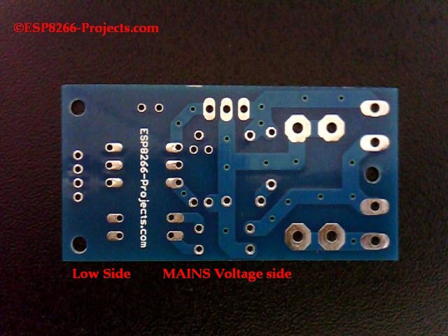
WARNING!! You will work with LIVE MAINS!! Deadly zone!!


If you don't have any experience and are not qualified for working with MAINS power I will not

ecourage you to play arround!

----------------------------------------------------------------------------------------------------------------------------------------------------------------------------

Because the previuos MPSMv2 was designed more as a DevBoard for MAINS switching application and the FUSE and MAINS input / output /filtering unit was keept separatelly, has created some confusion and a lot of talks about, Hackaday thread included :).

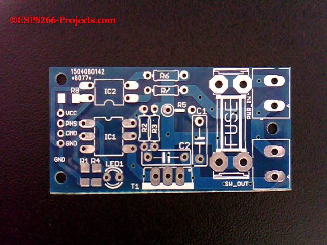
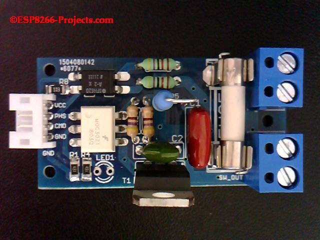
So, this time, as people were asking for a more general usage module that can be used with existing Setup/Environments, you have on the same board, fuse and connectors to directly connect de MPDMv3 module to MAINS, Lightbulb/Lamp and your MCU Board. Just add a proper sized Choke EMI suppression filter and that's it.

  • Zero Crossing Detection

    Johnny05/15/2015 at 08:18 1 comment

    Mains power is comprised of an alternating current that flows in one direction and then in the other, along the cable, at the rate of 50 or 60 cycles per second.

    The number of cycles in one second is called the frequency. The frequency is given in a unit called hertz (symbol Hz) where 1 Hz = 1 cycle per second .

    The value 50 or 60Hz is dependent on the countries power system. The current alternates back and forth changing direction at the zero point.

    If we will to look at the waveform (yellow) with the Osciloscope it would appear as a sinusoidal shape. Drawing a line through the middle and this is what is called the zero crossing point. At this instant in time no current is flowing in either direction.

    Yellow : AC line - 50Hz

    Blue : ZCD module output

  • General considerations

    Johnny05/15/2015 at 08:14 0 comments

    There are several types of dimmers generally available. These are used for resistive, and inductive loads, such as incandescent,cold cathode and low voltage (inductive) lamp sources. Note that not all electronic transformers used for low voltage lamps are suitable for dimming by Triac or Thyristors dimmers. In case of Thyristors you need 2 of them as Thyristor is a Unidirectional device and because AC power flows in both directions!

    For resistive loads ON-OFF only jobs (no dimming required) a winning combination is between MOC304X for Triac driver (Zero voltage crossing one) and a good quality Triac, decently sized at the power needs.

    In case of dimming you DON'T want to use a zero crossing voltage one! And this is because of the way the dimming process is going and depending on our own ZCD (zero cross detection) function. In our case zero cross detection is done by the biphase optocoupler as in the schematic below.

View all 2 project logs

  • 1
    Step 1

    If you want for your own experiments to order MPDMv3 bare PCBs only, you can also do it directly at the PCB House:

    http://dirtypcbs.com/view.php?share=6077&accesskey=6d39638a132d55b23b6d2eab8d095bba

  • 2
    Step 2

    Soldering process is as simple as 1-2-3, most of the parts are big thru hole ones. Just a 5 minutes soldering fun :)

  • 3
    Step 3

    For testing without connecting the MAINS line and Load, just solder also the LED1. It has no role in the dimming process, just a good testing and "debuging" tool :)

View all 4 instructions

Enjoy this project?

Share

Discussions

Similar Projects

Does this project spark your interest?

Become a member to follow this project and never miss any updates