0%
0%
$5 Wifi (RGB enabled) LED Dimmer w/ ESP8266
A super tiny LED dimmer, controllable from any device, based on the ESP8266. Doesn't require an arduino or rasp pi.
 Tom Clement
Become a Hackaday.io member
Already have an account? Log in.
Just one more thing
To make the experience fit your profile, pick a username and tell us what interests you.
Pick an awesome username
hackaday.io/
Your profile's URL: hackaday.io/username. Max 25 alphanumeric characters.
Pick a few interests
Projects that share your interests
People that share your interests


 Hoyoung Lee
 Tamojit Saha
 Paul Gallagher
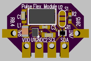
 Chris Hamilton
Tom, Thanks so much for this awesome project. Can you please advise on a mosfet to handle a load of 20 amps. I am looking to implement your design on a car (Jeep Wrangler) to control off road lighting through MQTT and allow pwm control to the lights but the mosfets you used aren't capable of the current I need. Thanks again so much for documenting your project I have been looking for something like this for ages.