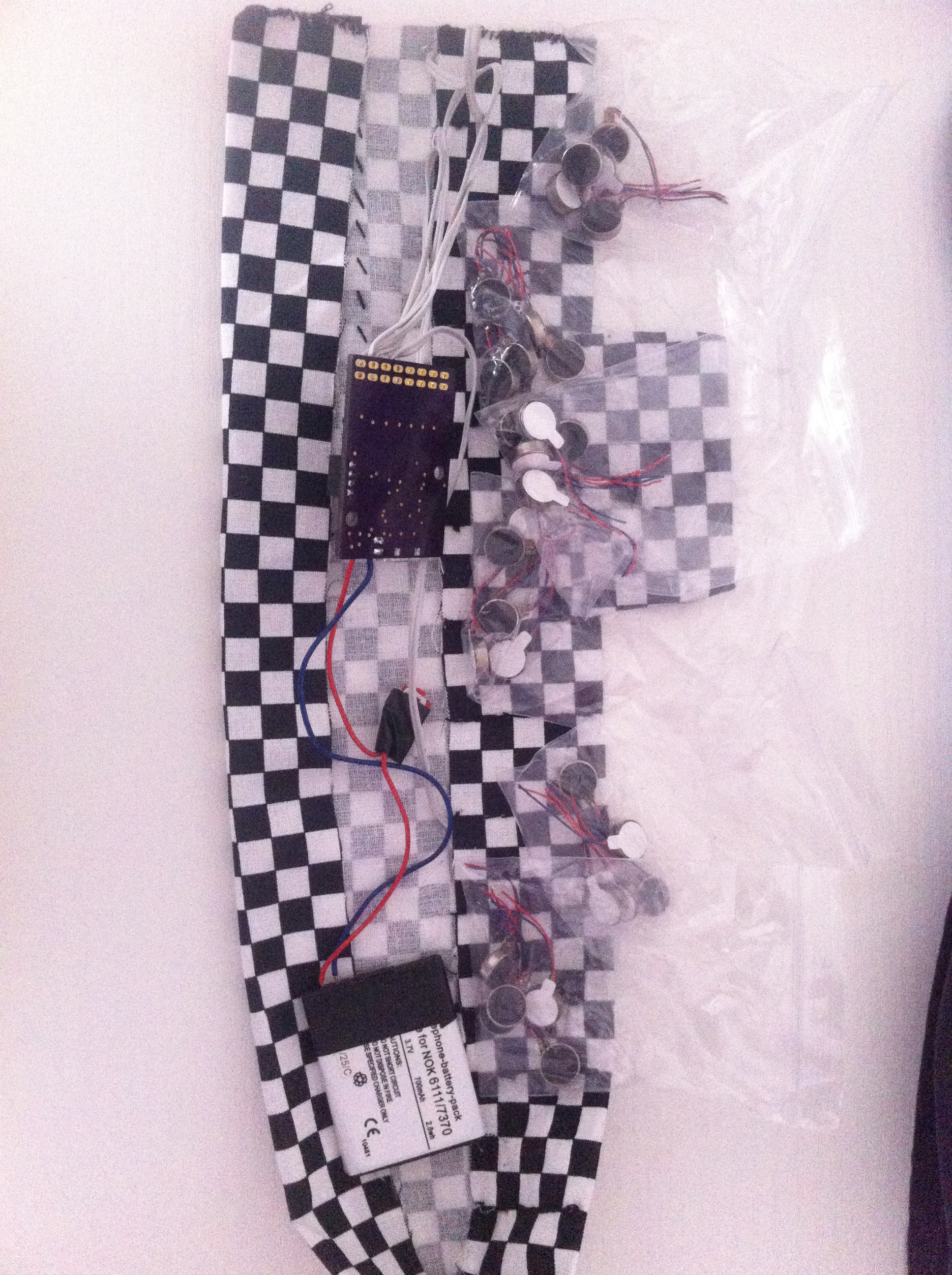
Through ebay I was able to purchase 30 additional motors from China. Before that point, I used to order the vibration motors from the following link: http://www.seeedstudio.com/depot/Mini-vibration-motor-20mm-p-2300.html. The seeedstudio order is more reliable but a lot more expensive. By chance, the ebay motors seem to be from the same kind. There are some small differences with the DC resistance between each motor and also the resistance is changing after rotation. Maybe it's an indication for decreased commutator quality?!

Changing Hard- and Software at github
I have tagged the four motor version in source code and in design at github. If anyone has already started to build the old version, you could still use the correct (older) versions:
TheSixthSense_XMega is tagged with V1.0
TheSixthSense-PCB is tagged with V1.1
I would prefer to use the newest version with eight motor support.
Whats new
There aren't so many (eight / 16 bit) PWM Pins on a XMegaE, because I2C data- and clock line is blocking two PWM pins. Thats no problem cause the pwm resolution doesn’t need to be very high. Its enough to have 32 steps to adjust the vibration force to your needs.
I changed the hardware PWM to a software BAM (http://www.batsocks.co.uk/readme/art_bcm_3.htm)
Here is my implementation to init a timer with 4 compare interrupts an overflow interrupt using the Atmel Software Framework:
#define TIMER_RESOLUTION 500 // 250 HZ at 2 MHz and div = 8
//init BAM with one timer to supply 8 motors with 250 Hz
void init_bam(void)
{

/* Unmask clock for ... */
tc45_enable(&TCC4);

/* Configure TC in normal mode */
tc45_set_wgm(&TCC4, TC45_WG_NORMAL);

/* Configure period equal to resolution to obtain 250Hz */
tc45_write_period(&TCC4, TIMER_RESOLUTION);

//no cc outputs
TCC4.CTRLE = 0;

//bam timing -> 5 Bit possible with ovf vector
tc45_write_cc_buffer(&TCC4, TC45_CCA, TIMER_RESOLUTION >> 4);
tc45_write_cc_buffer(&TCC4, TC45_CCB, TIMER_RESOLUTION >> 3);
tc45_write_cc_buffer(&TCC4, TC45_CCC, TIMER_RESOLUTION >> 2);
tc45_write_cc_buffer(&TCC4, TC45_CCD, TIMER_RESOLUTION >> 1);
tc45_set_overflow_interrupt_callback(&TCC4, ovf_interrupt_callback);

tc45_set_cca_interrupt_callback(&TCC4, cca_interrupt_callback);
tc45_set_ccb_interrupt_callback(&TCC4, ccb_interrupt_callback);
tc45_set_ccc_interrupt_callback(&TCC4, ccc_interrupt_callback);
tc45_set_ccd_interrupt_callback(&TCC4, ccd_interrupt_callback);

/*
* Enable TC interrupts
*/

tc45_set_overflow_interrupt_level(&TCC4, TC45_INT_LVL_LO);
tc45_set_cca_interrupt_level(&TCC4, TC45_INT_LVL_LO);
tc45_set_ccb_interrupt_level(&TCC4, TC45_INT_LVL_LO);
tc45_set_ccc_interrupt_level(&TCC4, TC45_INT_LVL_LO);
tc45_set_ccd_interrupt_level(&TCC4, TC45_INT_LVL_LO);
/*
* Run
*/
tc45_write_clock_source(&TCC4, TC45_CLKSEL_DIV8_gc);

}
As you can see it’s rather easy to setup the timer with ASF support.
Before you could call this function you should define the callback functions for the interrupts. The source code for every interrupt callback is mostly the same. You have just to define which bit should be modulated:
static void ovf_interrupt_callback(void)
{
soft_bam_process(0x01);
tc45_clear_overflow(&TCC4);
}

static void cca_interrupt_callback(void)
{
soft_bam_process(0x02);
tc45_clear_cc_interrupt(&TCC4, TC45_CCA);
}
...and so one.
The function soft_bam_process turns on and off all the motors you could add and you could add so mutch motors you have free digital pins.
Lets take a look in this function:
void soft_bam_process(uint8_t bitmask)
{
//error if adding motors without changing source
#if(MOTOR_NUM != 8)
#error (add more motors here)
#endif

if(motor_soft_bam[0] & bitmask) {
gpio_set_pin_high(M1_O);
} else {
gpio_set_pin_low(M1_O);
}

if(motor_soft_bam[1] & bitmask) {
gpio_set_pin_high(M2_O);
} else {
gpio_set_pin_low(M2_O);
}
Its good to have some precompiler errors if you try to add more motors and forgot to map this motors to there gpios. The motor_soft_bam array is the new compare register array you could change from the main loop. If you set one 8 bit value to zero the corresponding motor will not vibrate. A value of 31 turns on all bits and you will have the full DC voltage from the battery at the motor pins. The processing power to map the bits to their corresponding gpios is very light.
Result
In theorie accuracy of the cardinal direction could be maximum ± 22.5 ° with eight motors. But there are some additional errors:
- positioning of the motors at the anklet
- sensitivity of the shin/skin
- reading and filter errors from sensor or software
Nevermind, I like the eight motor version. It is a lot more accurate than the four motors version. You could really feel the huge differences to the old version.
TODOs
It’s a good idea to make this anklet a bit smarter and more useful for people without a debugger. Of course the solution in this year is bluetooth low energy. TI has a new BLE Processor, this time with a Cortex M3 on the chip. I liked the old Sensortag from TI a lot and I have a hole bunch here but I never reprogrammed it because of the old 8051 microcontroller core (free compiler problem). Things changed and TI was releasing the CC2650 this days.
The new Sensortag has a 9D Sensor (MPU-9250) and an extension header… Enough to control the motors direct from the Sensortag CPU…
I will order a Sensortag and test this out...
 Sebastian Foerster
Discussions
Become a Hackaday.io Member
Create an account to leave a comment. Already have an account? Log In.