 Voja Antonic
This project is based on PIC24EP512GP806, which has 52K (53,248 bytes) of Data memory and 512K of Program memory. CPU speed is 140 MHz (70 MIPS), but here it runs at 120 MHz (60 MIPS).
Due to the limited amount of RAM, frame resolution is 220x220 pixels, which takes 48,400 bytes. The rest of 4,848 bytes is used for housekeeping. One pixel takes only 6-bit (monochromatic), and bits #6 and #7 are used in image processing routines, as there is no auxiliary frame buffer. There is the 8-bit ADC (National Semiconductors ADC1173), used for sinle frame grabbing (6 bits are used).
To make the software development and adjusting process possible, there is also the VGA video stage, which enables full reproduction of the frame buffer, plus some other digital data (important status messages, variables and memory dump). This video stage is fully software supported.
I/O communication is via RS232 port. During the development process, the same port is connected to the simple terminal unit.
The whole program is written in assembly language. One ball number recognition takes about 450-500 ms, including about 110 ms for frame fetch.
This is my third try to make the same project. I built the first one about five years ago, you can see it on https://www.youtube.com/watch?v=napA-fwdxeY It worked fine, but there were problems with single digit numbers rotation. I started again from scratch two more times, and I learned some things doing this - for instance, that the recognition itself is the peace of cake, compared to ball and number locating and angle detection. So I leaved the first neural network idea and made the recognition algoritmic - it also works fine, and there is no network training.
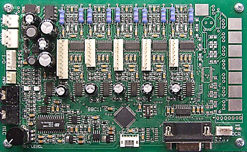
Don`t ask why the PCB is skewed, it was the requirement of the system in which it was embedded.
There is not much to say about hardware, as nearly everything is under software control.
Composite video signal, typically from the low-cost "cube" TV camera, is fed directly to the 8-bit ADC. The input voltage range for ADC1173 is 0-2V and, as one pixel of video data contains 6 pixels, there is no need to amplify the signal. The first half of dual comparator LM393 serves as sync detector, and the other half is for automatic offset. There is also the video amplifier MAX4012, if the external video out is needed.
VGA video out is not necessarry during operation, but it is very usefuul in development and adjustment process. Bits 0-5 are fed directly to the resistor ladder, and bits 6 and 7 are binary blue and red signals, respectively. As bits 6 and 7 are intensively used in picture processing, mainly for component selecting and grouping, this concept is very helpful during development, and yet simple. Some parameters are also diplayed, and also the RAM dump, which can be scrolled via extarnal terminal keyboard.
1. Frame fetch
The main problem with Bingo balls is that they are polished and glossy, so it is hard to avoid light reflection. That is why the special process of double expousure is used.
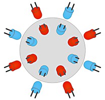
16 white LEDs are arranged in 2x2 groups. There are inner leds which illuminate the center of the ball, and the outer ones for ball edges. Each group can be addressed for "odd" and "even" LEDs, so MCU can illuminate individual ball slices. Two exposures are made, first with the group of LEDs which are marked as red on the drawing, an the second with LEDs marked as blue (of course, all of them are actually white). During the second exposure, each pixel which is lighter than in the previous exposure, will be ignored, and only the darker ones shall be written in frame buffer. If there is no extra light which comes from the outside, the result is perfect exposure, with no shiny areas.
There are two disadvantages of this process. The ball must be motionless during both exposures, and it takes a lot of time. Most of low-cost surveillance cameras have some persistence, so you must wait for one more dummy frame between LEDs setting and exposure. For PAL cameras, one frame takes 20 ms and in the worst case the whole described process takes 5x20 ms, plus about 15 ms for frame conditioning (digital adjusting of black and white levels and contrast enhancement). For NTSC cameras, this time is about 20% shorter.
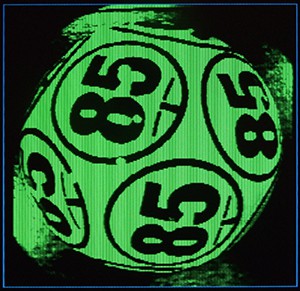
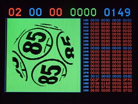
The next three photos show the first, second and combined exposure. They are taken from VGA monitor by photo camera. Same is with all other photos on the next pages.
First exposure:
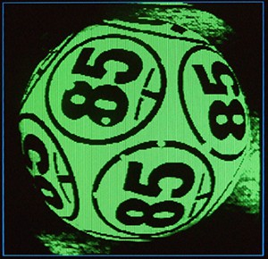
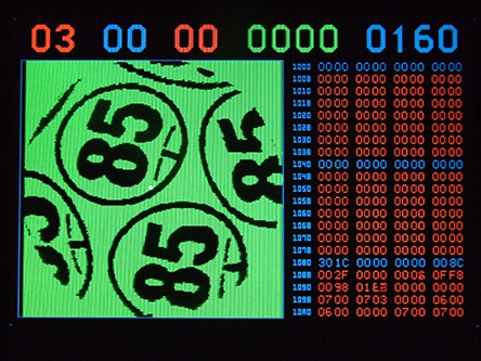
Second exposure:
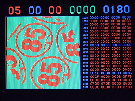
. Combined image:
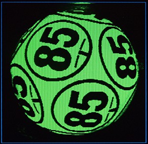
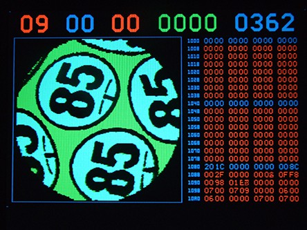
After the frame fetching, data in frame buffer is rendered to mach 6-bit monochromatic pixel depth. There are two fixed variables, similar to contrast (gain) and brightness (offset), which are used to adjust every pixel, in the range 1...63 (zero is not used in the picture representation, as it will have some special role in later processing)

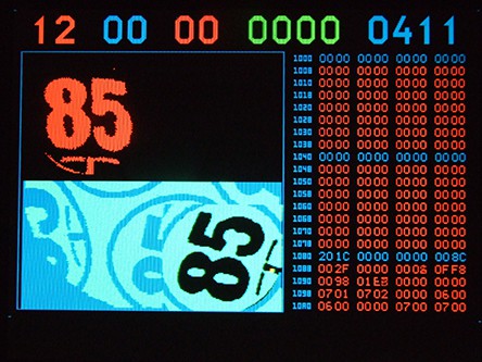
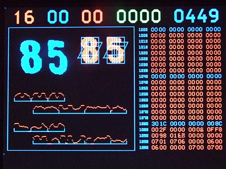
All photos are took by the camera from VGA monitor. Here is the top row explanation:
01 Processing step number
00 Recording step (used only in number recording process)
00 Final result (ball number) or error report
0000 Final guess rate in %, ((best result) / (second best result) - 1) * 100
0111 Total processing time in miliseconds
The numeric field at the right side is 16-bit memory hex dump. It can be scrolled up and down.
2. Ball location
To locate the ball precisely, the X, Y coordinates for centroid (geometric center) ar calculated, using formulas Cx = ∑CixAi / ∑Ai and Cy = ∑CiyAi / ∑Ai, where Cx, Cy are X, Y coordinates and A is the value of every pixel. As the background is predominantly black before this step, Cx, Cy will be in the center of the ball. Then the whole picture is moved so that the centroid is at coordinates 110,110, which is at the center of the frame. The center is marked with 2x2 red pixels.
Next, the averade diameter is measured, calculating the average pixel value for different diametres. The highest drop of average value (relative to the previous one) is considered as the ball diameter. Then, the background (every pixel which is outside of the diameter) is set to "white", or, more specifically, green (value 63).
Those two steps take 38 ms, which is not bad for the small microcontroller processing 220*220 matrix. One part of credit for that goes to assembly language, and the other one to lookup tables which are used instead of trigonometric calculations.
3. Stretching
If you compare this image to the previous one, you shall see that the center of the ball on the picture is mostly unchanged, and the edges are stretched so that spherical deformations are minimized. It is, of course, impossible to represent the spherical image on the 2D plane, but this edge stretching enables using numbers which are not exactly in the center of the image. This step took 11 ms.
4. Unsharp mask
Similarly to Photoshop's Unsharp Mask finction, in this step the separated image is made with blurred image. As there is not enough space to do it in the whole frame buffer size, it is performed with (1/5) * (1/5) resolution (every 5th pixel in every 5th row). This unsharp mask will be used for better selecting of "ink" pixels, relative to "paper" pixels, which will be taken not from the main frame buffer, but from the auxilary one.
5. Components selection
Every pixel is tested for Ink (main buffer) and Paper (aux buffer with blured image) and, if the difference is greater than treshold, bit 7 (red) is selected, otherwise bit 6 (blue) is selected. This gives the binary image, but green portion (bits 0...5) is still held.
6. Holes and scratches
This is pre-processing step for noise reduction. Every pixel with Ink bit set, is tested for neibours with Paper bit set, like in Conway's Game of Life . If six or more bits are Paper, then that ink is replaced with Paper. Same is with opposite situation (Paper surrounded with 6 or more inks is replaced with ink). So the small errors are corrected.
7. Component shrink
In the next step of pre-processing, all ink pixels at the edges are reset to Paper. This process can be repeated, Maybe there should be some more Shrink steps, maybe also combined with Expand steps. This is the empiric question, so I need more experimenting.
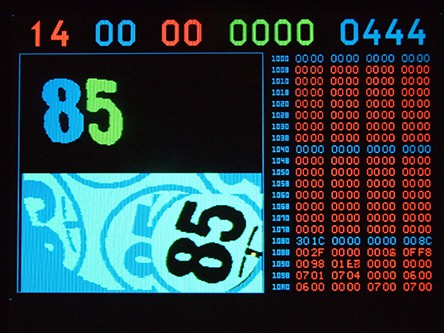
8. Invert selection
The selection is inverted, but in this step the background (outside the ball) will not be selected, but reset to black. White background was needed for proper Ink selecion, now it is better to keep it black.
9. Components list
The list of all components is made (all Paper componnets, not ink!) and all their parameters are measured and registered. Those parameters include X and Y dimensions, X and Y center coordinates, number of selected pixels, and the Euclid`s distance from the center of the frame.
Obviously, this is the hard task for MPU, as it takes almost 150 ms to execute. All standard connected components algorithms use aditional buffers which take as much more RAM as the main frame buffer, so I had to develop my own algorithm for "poor man's" processing unit with limited data memory.
10. Best circle selection
Here the decision is made which of the components from the list are circles that surround numbers, and the rest of them are flushed from the list. Then, the "winner" is found (the one which is closest to the center of the frame). Its coordinates are now very important, especially X and Y center.
11. Angle detection
This step is specific for each ball design type, as it searches for the underline pattern circularly. In this case, it is "T" pattern with short and thick medium line. This pattern is automatically adjusted to the circle diameter, which is measured two steps before. The resulting angle (in 0...511 range for full circle) is marked here as 2x2 red+green pixels, just for visual control during software development. It is visible as the yellow dot at the next image.
12. Rotate selected
The "winning" area is moved to the bottom right of the frame buffer, and the rotation is performed at the top left quater of the screen. Instead of intensive and slow trigonometric calculation, lookup tables are used again, so it took only 38 ms.
13. Select broad lines
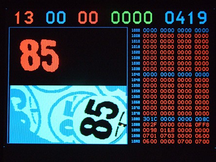
Image (or at least its top left quarter) is cleared, selecting only ink pixels which are surrounded by massive ink areas. This eliminates not only small errors caused by noise, but also underlining markers.
14. Connected components list is made
New connected components list was created, but this time not for Paper, but for ink pixels. If more than two components are detected, the error is reported. Again, all coordinates and component dimensions are registered, as it will be necessary in the next step.
15. Components scaling
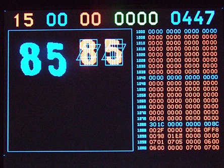
All green pixels (right-hand digit) are moved to the right, to avoid colision during components scaling. Now, the scaling is performed in the top right part of the graphic screen.
The special borders are drawn, to mark the areas for histogram creation. Those borders are not used for program, but only for visual check during software development.
16. Histograms
Now, the histograms is created for each fenced area. Simply, ink pixels are counted for each member of the area, and the result is placed in the table.
17. Mean Squared Error and voting
This is the last step of recognition process. All histogram members for the first digit are squared and compared to the previously recorded and squared histograms for known numbers (this process is not described here). All differences are added and the table of 10 sums is created. Then the decision is made which one is the winner, you can see the recognized number at the top row of the screen.
Also, the next best match is found, and the rating for the winner is calculated, using formula ((best result) / (second best result) - 1) * 100. The result shows the ratio between first and second best number in %.

Conclusion
This OCR controller will be embedded in the larger project of automatic Bingo machine, which is also under develompent. You can see the ball recognition stage here:
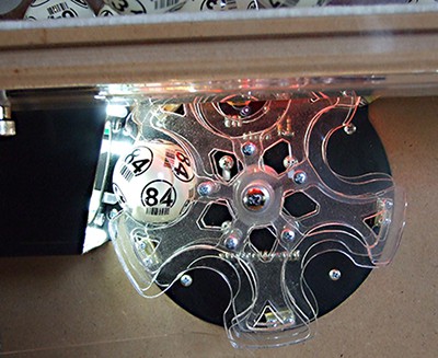
When the error is reported, the ball should be rotated a little and the whole process repeated. With this Bingo prototype, it is performed so that the lower carousell (visible at the photo) shakes CW-CCW violently for a few degrees. All mechanical parts are driven by stepper motors, so this requires no extra hardware.
At my first OCR project, I tried the neural network recognition, but I saw that the recognition itself is easy to do, so I replaced it with the much more simple algoritmic software. The main problem is not recognition itself, but proper locating and rotational angle measurement for numbers.
I also noticed that it is much better to use the lens with the higher focal length, so that the bigger area of the ball is covered. That will minimize the problems with bad ball angular positioning, when all numbers on the ball are far from the image center.
And the last conclusion: I enloy doing such projects.