 Voja Antonic
This project is based on PIC24EP512GP806, which has 52K (53,248 bytes) of Data memory and 512K of Program memory. CPU speed is 140 MHz (70 MIPS), but here it runs at 120 MHz (60 MIPS).
Due to the limited amount of RAM, frame resolution is 220x220 pixels, which takes 48,400 bytes. The rest of 4,848 bytes is used for housekeeping. One pixel takes only 6-bit (monochromatic), and bits #6 and #7 are used in image processing routines, as there is no auxiliary frame buffer. There is the 8-bit ADC (National Semiconductors ADC1173), used for sinle frame grabbing (6 bits are used).
To make the software development and adjusting process possible, there is also the VGA video stage, which enables full reproduction of the frame buffer, plus some other digital data (important status messages, variables and memory dump). This video stage is fully software supported.
I/O communication is via RS232 port. During the development process, the same port is connected to the simple terminal unit.
The whole program is written in assembly language. One ball number recognition takes about 450-500 ms, including about 110 ms for frame fetch.
This is my third try to make the same project. I built the first one about five years ago, you can see it on https://www.youtube.com/watch?v=napA-fwdxeY It worked fine, but there were problems with single digit numbers rotation. I started again from scratch two more times, and I learned some things doing this - for instance, that the recognition itself is the peace of cake, compared to ball and number locating and angle detection. So I leaved the first neural network idea and made the recognition algoritmic - it also works fine, and there is no network training.
Don`t ask why the PCB is skewed, it was the requirement of the system in which it was embedded.
There is not much to say about hardware, as nearly everything is under software control.
Composite video signal, typically from the low-cost "cube" TV camera, is fed directly to the 8-bit ADC. The input voltage range for ADC1173 is 0-2V and, as one pixel of video data contains 6 pixels, there is no need to amplify the signal. The first half of dual comparator LM393 serves as sync detector, and the other half is for automatic offset. There is also the video amplifier MAX4012, if the external video out is needed.
VGA video out is not necessarry during operation, but it is very usefuul in development and adjustment process. Bits 0-5 are fed directly to the resistor ladder, and bits 6 and 7 are binary blue and red signals, respectively. As bits 6 and 7 are intensively used in picture processing, mainly for component selecting and grouping, this concept is very helpful during development, and yet simple. Some parameters are also diplayed, and also the RAM dump, which can be scrolled via extarnal terminal keyboard.
1. Frame fetch
The main problem with Bingo balls is that they are polished and glossy, so it is hard to avoid light reflection. That is why the special process of double expousure is used.
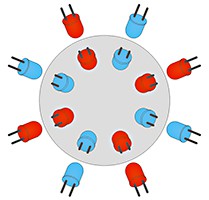
16 white LEDs are arranged in 2x2 groups. There are inner leds which illuminate the center of the ball, and the outer ones for ball edges. Each group can be addressed for "odd" and "even" LEDs, so MCU can illuminate individual ball slices. Two exposures are made, first with the group of LEDs which are marked as red on the drawing, an the second with LEDs marked as blue (of course, all of them are actually white). During the second exposure, each pixel which is lighter than in the previous exposure, will be ignored, and only the darker ones shall be written in frame buffer. If there is no extra light which comes from the outside, the result is perfect exposure, with no shiny areas.
There are two disadvantages of this process. The ball must be motionless during both exposures, and it takes a lot of time. Most of low-cost surveillance cameras have some persistence, so you must wait for one more dummy frame between LEDs setting and exposure. For PAL cameras, one frame takes 20 ms and in the worst...
Read more »


 JTKLENKE
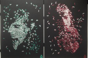
 Christian Walther
 Bruce Land
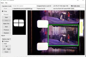
 Lars Lund Hansen
Try posting topics as different project logs :)