Hackaday Weekly Prize Winner, Stickvise
The Muffsy Hifi Dual Power Supply is one of the winners of a Stickvise!
What is it for?
This regulated power supply is intended for audio applications that don't require a lot of power. Typically pre-amplifiers , fully discrete or based on operational amplifiers.
Features
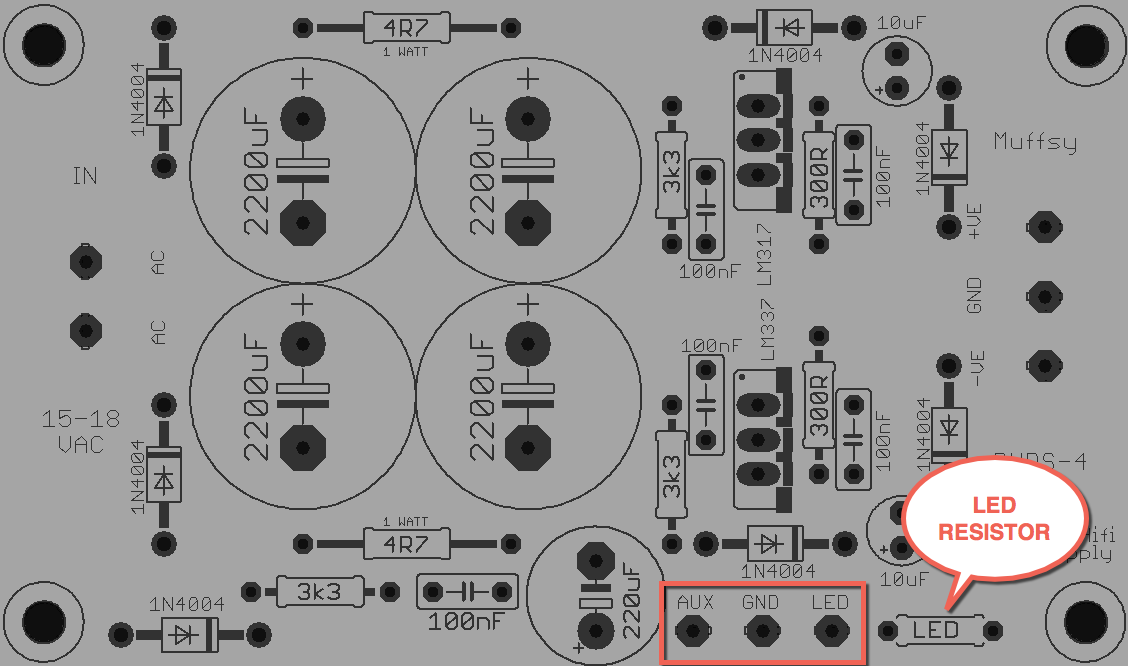
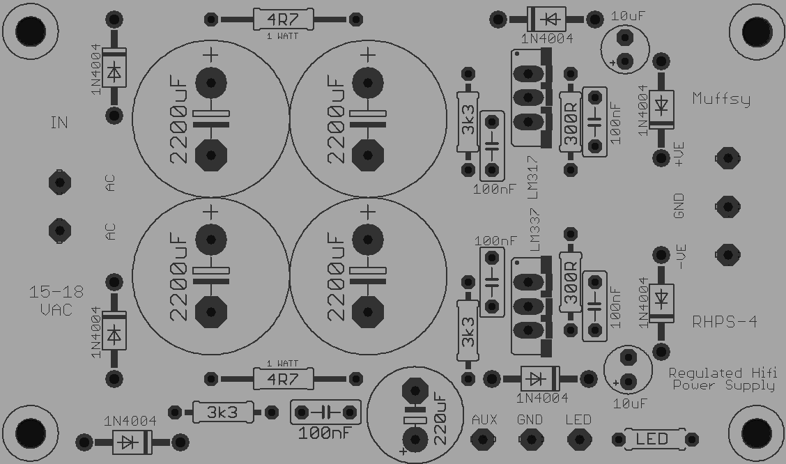
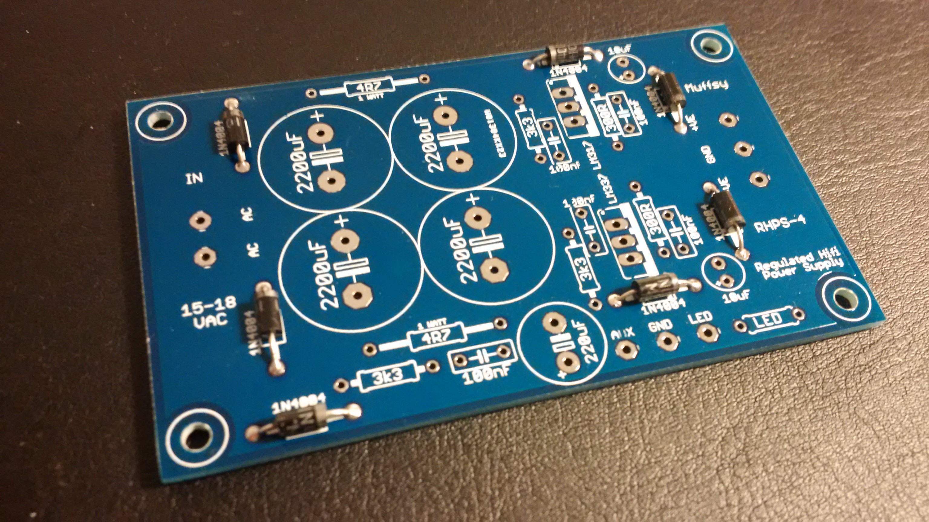
This PSU takes a single 15-18VAC input and gives dual 15VDC output.
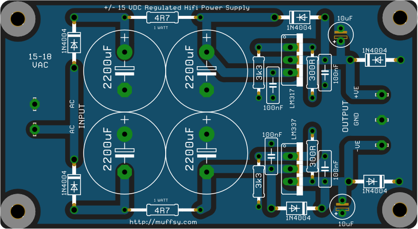
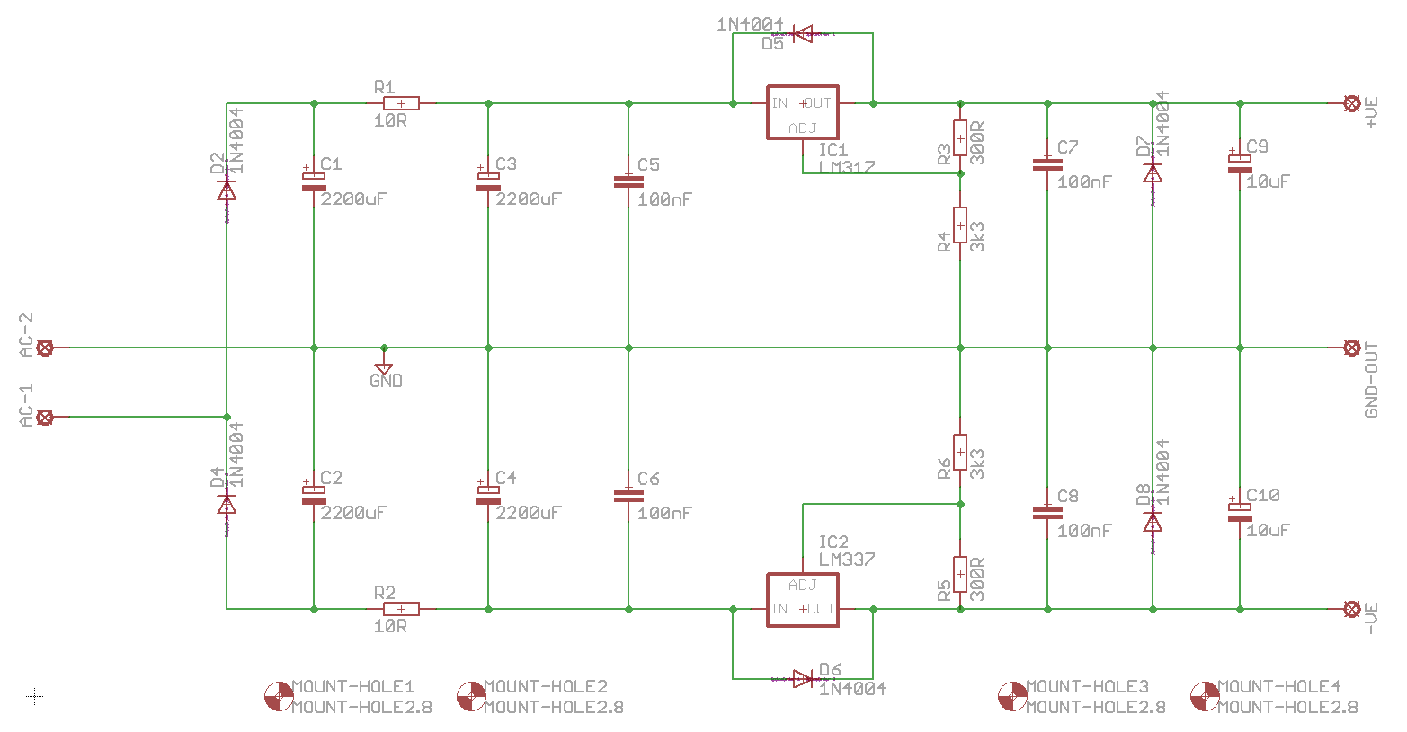
It is dead simple, has fantastic performance, and consists of the following stages:
- Single 15-18VAC input
- Two half-wave rectifiers
- Voltage doublers
- LM317/337 voltage regulators
- Filter capacitors
- Regulated +/- 15VDC output and ground.
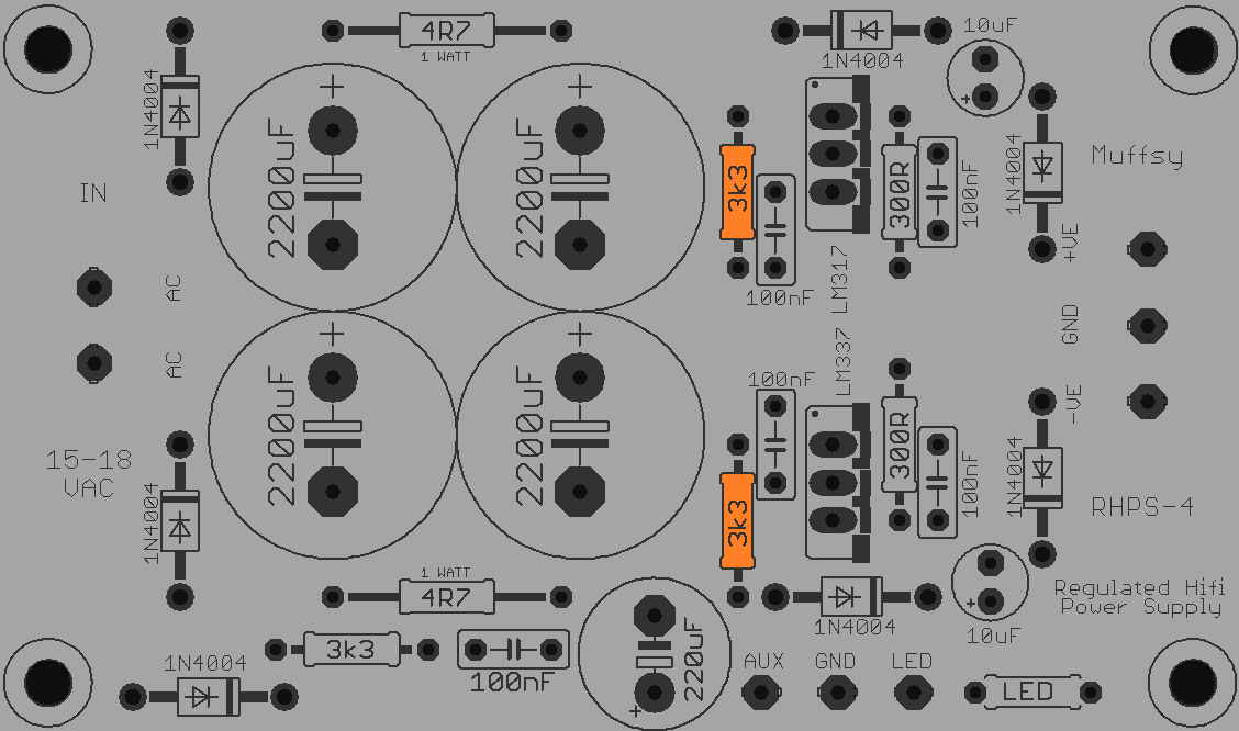
And, as regulated power is limited:
- Unregulated AUX power ~20-23V
- Extra power output with resistor for LED
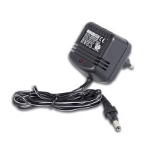
By using a wallwart, there is no risk of electrocution or fires.
Performance
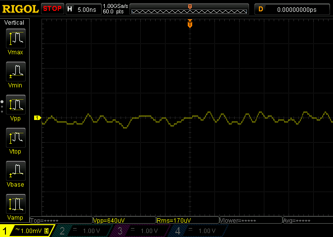
The PSU performs superbly. Used together with the Muffsy Phono Preamp PP-2 or the new PP-3, it has only 0.1 mV noise on the DC output. Well below the Power Supply Rejection Rate (PSRR) of any operational amplifier, and very suitable for discrete circuits.
The PSU gives up to 100 mA of current when used without heatsinks. That's enough to power four phono stages. Mounting heat sinks on the LM317/337 will give you up to 200 mA.
The AUX power gives an additional (unregulated) 500 mA of current, or more, depending on your transformer.


 Denis
Denis
 euchcat
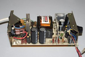
 Keith
Keith
I just built your PS from the PDF pcb. Thanks for your contributions, mine has the lower rail with a voltage difference of 101 mV from the top rail, is that okay? Also I notice the negative rail also shows a higher ripple on my scope. If I'm measuring ripple correctly I don't know.