Close
0%
0%

Open Source Bench Top Power Supply

We start simple: with an open-source variable voltage power supply, which, for now, will use a modified computer PSU.

Similar projects worth following
I want this project to be simple enough for any student (as myself) to be able to do, but at the same time complicated enough that you learn a lot of stuff. I have already started on it, and it will work like this:

Using two rotary encoders you will be able to select an output voltage between 1 and 12V (10-11V more realistically) and a maximum output current between 0 and 1.5A. The steps with which you will be able to specify these voltages and currents are at least 15mV for the voltage and 10mA for the current.

The rotary encoders will be read by a microcontroller (debating whether to use a PIC or just stick to an Arduino for now), which will send a PWM signal accordingly. This signal will be filtered so as to obtain a DC voltage (2mV ripple) to control the voltage regulator.

Voltage & current will be read to the display using a voltage to frequency converter circuit (which I'm working on) as this would drastically increase the resolution of the voltage reading.

This is how the voltage sensing part of the project will work:

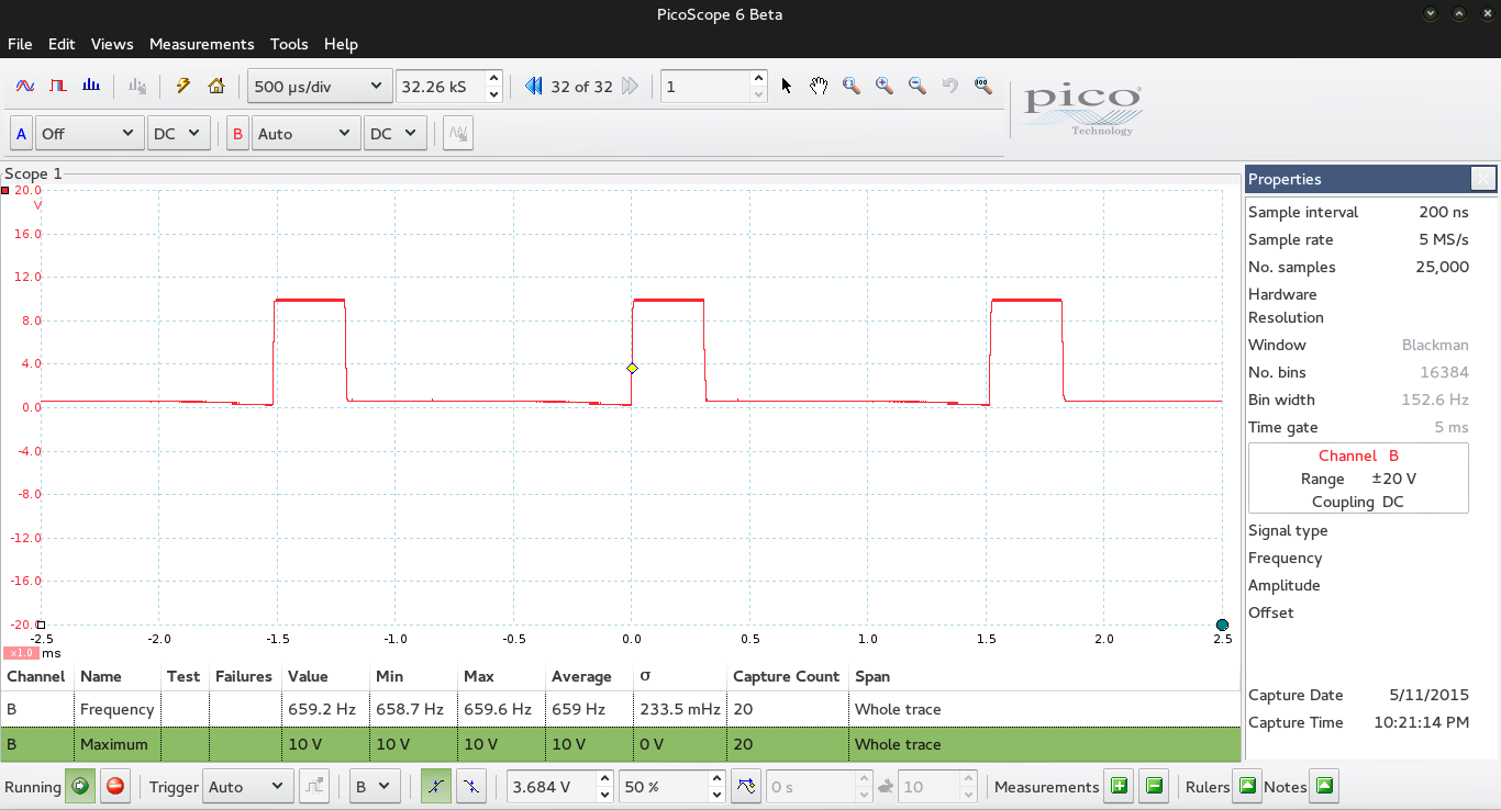
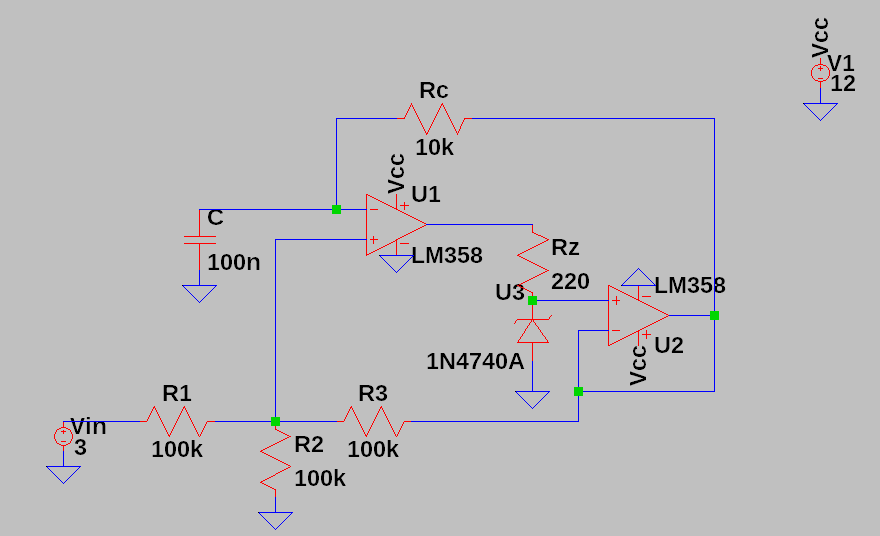
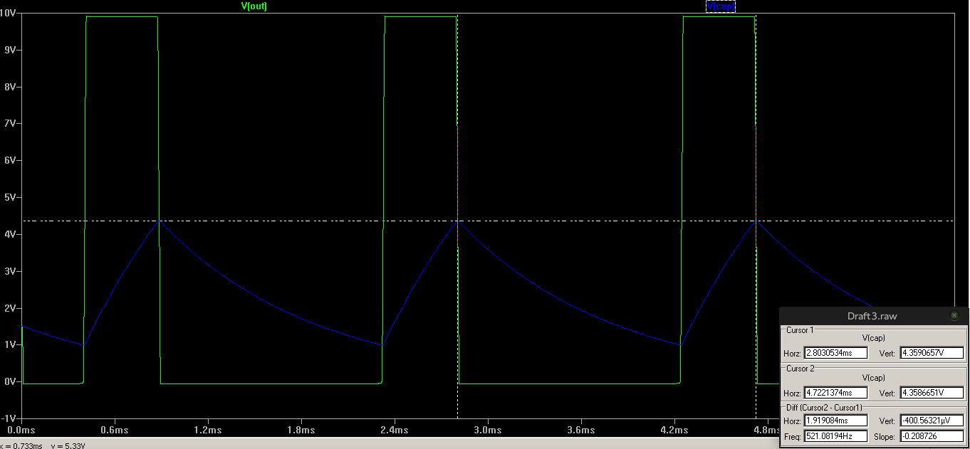
The voltage to frequency converter circuit is just a Schmitt Trigger -like circuit, whose hysteresis allows it to have different threshold voltages which depend on the input voltage (the voltage read at the output of the power supply). After calculated, using this circuit I can successfully modify the frequency of a square wave. Why do I complicate myself like that? I feel like I would get a much better resolution on the output voltage which, remember, swings between 1 and 12VDC (10 to 11 more realistically, I'll see that when I build the circuit) so a microcontroller with an 10 bit ADC wouldn't suffice for, say 10 mV resolution.

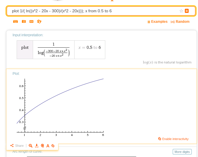
This is the calculated output frequency of the circuit with relation to the input voltage (I plot from 0.5 to 6V input because that's the region where this equation is as linear as possible).

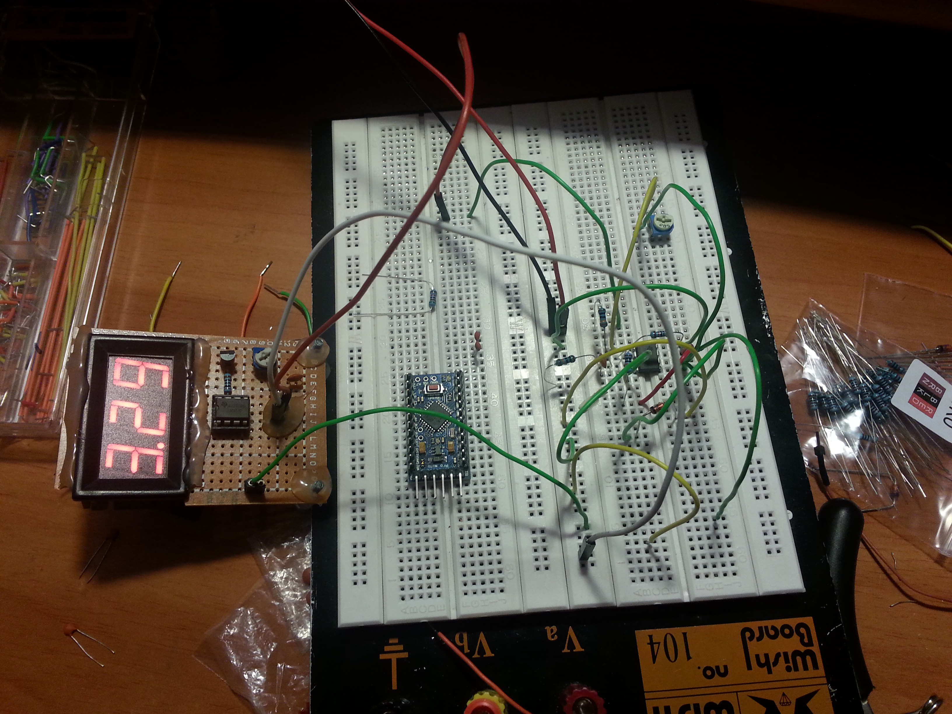
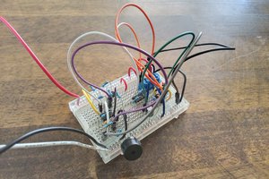
I will do some simulations, maybe even build the circuit, this week-end.

I am sorry if the project isn't intelligible yet, it is late, I am tired, and I really want to enter the Hackaday Prize. I will do this project, I need a good bench top power supply, and I will revise this project page and make everything crystal clear when I'm done so that everybody can follow what I did.

  • 1 × Nokia 5110 LCD For displaying voltages and currents. Adding more functionality later
  • 1 × Arduino Pro Mini 3.3V This will read and set the voltages, as well as read the rotary encoders.
  • 1 × LM358 Amplifier and Linear ICs / Operational Amplifiers
  • 1 × Computer ATX Power Supply Power supply taken from an old computer. Will supply 12V to be stepped down by the circuit.

  • How to solve the fact that practice is different from theory

    acp.calin05/11/2015 at 19:49 0 comments

    As expected, practice is different from theory and simulation. The calculated frequency that circuit should give at 3.3 volts is 655 Hz, the real frequency, as shown by a very cheap PC based oscilloscope is 660 Hz and by a Fluke 177 multimeter 681 Hz. If we take the first value, 660 Hz, we're not too far from 655 Hz which looks actually promising. Note that the maximum voltage is exactly 10V. The frequency is a bit bigger than expected, which seems wrong, because a resistance (for example the output resistance of the LM358) should lower that frequency. Something else must be there, I will check. I'll have to search for a good oscilloscope at my university and measure that frequency again.

    Anyways, I have a plan to correct/solve this error. First I need to make a simple frequency counter on my Arduino, since that's what I'm gonna use in my power supply. Then I will make about 100 measurements at different well known input voltages (from 1 to 12V) and note the frequencies at those voltages. Then I'm gonna plot those points in QtiPlot or Matlab and do a polynomial interpolation on them to get the function that describes these points. After that I can just use this function to determine the frequency with relationship to the voltage, or use it to determine some kind of equation to describe the error for the formula I calculated.

    I'll also try to do some improvements to the circuit so as to minimize any quantity that could have an unwanted effect on the output frequency. I'm also thinking about limiting the minimum output voltage of the circuit, as I saw on my crappy oscilloscope (which I don't really trust) that it gets below 0V, which doesn't seem logical to me. If I manage to do that I can skip the interpolation part and make a circuit that will work even if I change the resistances.

    The circuit is made on a breadboard.


  • What would I use a Teensy LC for?

    acp.calin05/09/2015 at 19:41 0 comments

    The whole goal of my power supply is that its central brain should be a microcontroller, which should be able to control everything about the power supply. The current Arduino I'm using only has 8 bit DAC resolution, which obliges me to make 4 separate output stages in order to control my output voltage with my desired resolution. The 12 bit DAC resolution of the Teensy LC would mean I would only need one stage to set the voltage and I could set the voltage with an even higher resolution. That would need some adapting to my filter because of the lower frequency of the PWM signal (11.7 kHz vs 31.25 kHz on my 3.3V Arduino Pro Mini), but nothing unmanageable (I assume the DAC of the Teensy board is the same as for the Arduino, in that it generates a PWM signal and not the literal voltage). However, a Teensy would greatly simplify the end circuit and give me mode power to do all kinds of things with that power supply.

    So yeah, I could use a Teensy :)

  • Voltage to frequency conversion circuit

    acp.calin05/09/2015 at 09:25 0 comments

    The voltage to frequency conversion circuit is the following:

    The zener diode has a zener voltage of 10V.

    After calculating, the equation which describes the output oscillation frequency with relationship to the voltage Vin applied at the input, assuming Voutmax = 10V,of the circuit is:

    \color{White} \large Frequency =  \frac{1}{ R_{c}C} * \frac{1}{ln(\frac{V_{in}^{2} - 20V_{in} - 300}{V_{in}^{2} - 20V_{in}})} For the given values of Rc = 10k ; C = 100n and Vin = 3V, the calculated output frequency is 518 Hz while the simulated one is 521 Hz. Not bad, the errors are probably there because of the output resistance of the op-amp. I thought of a nice method to describe and eliminate that error in the case I don't find the output resistance of the LM358.


View all 3 project logs

Enjoy this project?

Share

Discussions

Similar Projects

Does this project spark your interest?

Become a member to follow this project and never miss any updates