 RasmusB
This is the new lid that I have designed for the servo.
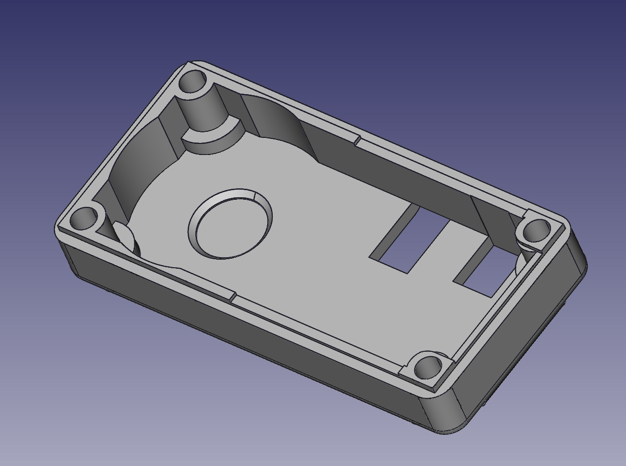
Why a new lid? There are two reasons:
1) The new PCB is thicker than the original. If I didn't modify the inner lip, it would interfere with the circuit board and I wouldn't be able to get the lid seated properly. You can see the cutout on the right side of the servo. It's only .35mm deep, but that small cutout makes the difference between a proper fit and a crooked lid. The servo is ultimately held together by the four screws in the corners, going into the top of the servo. If the lid is not in its proper place, the top of the servo can move which is bad.
2) I need to be able to debug the software even when the servo is installed. The smaller cutout to the right is for the debugger port itself (a 1.27 mm pitch SMT receptacle), and the larger one to the left is necessary because of pins protruding from my debugger adapter board. Not pretty, and I will remove the second cutout for the next revision. I'll also update the another ISP adapter so that it is not as cramped.
So I'm ordering this from shapeways, and I'll update with pictures of the real deal when I get it.
Discussions
Become a Hackaday.io Member
Create an account to leave a comment. Already have an account? Log In.