 Dan Berard
The preamplifier will be a small PCB mounted as close as possible to the tuning fork. It takes an input signal, which is divided by 100 by op-amp U1B and used to drive the tuning fork's oscillation, which should be around ~0.1 nm/mV. U2 is is a current-to-voltage converter used to measure the tuning fork's oscillation. The current should be in the nA range, at a frequency of ~25 kHz (but tuning forks are available up to 200 kHz, which would allow faster scanning), so I've used a high-speed, low-bias-current op-amp (OPA656) and routed a guard ring around the input node to keep leakage currents out. Getting a high enough bandwidth with a 10M feedback resistor requires that the parasitic capacitance across this resistor be less than 1 pF. U3 provides an additional gain of 10.
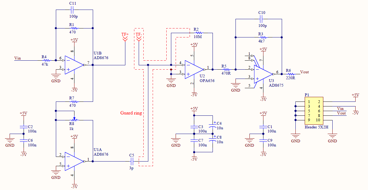
U1A inverts the excitation signal and drives a small capacitor, also connected to the I-V converter. By tuning the pot R8, the current can be adjusted to cancel out the current through the parasitic capacitance of the tuning fork electrodes and wiring. This way, the I-V converter only measures the piezoelectric response of the fork (which can be modeled as a series RLC circuit).
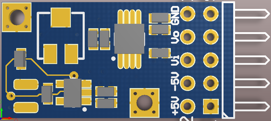
The PCB has 4 layers, and is 1" X 0.5". The two exposed pads at the bottom left are the connections for the tuning fork.
Here are some references I found useful. They really show that a tuning-fork oscillation controller can be built quite cheaply.
Discussions
Become a Hackaday.io Member
Create an account to leave a comment. Already have an account? Log In.