 technolomaniac
This project was designed for the Hackaday Worldwide LA Event and is used to interface a standard USB cable to the ESP8266-01 module. Having spent a fair bit of time using jumper wires and PTH resistors and regulators and such to make a typical 5V0 USB-Serial something ESP/3V3-friendly I decided to build a little board with a few features that simplified the whole workflow.
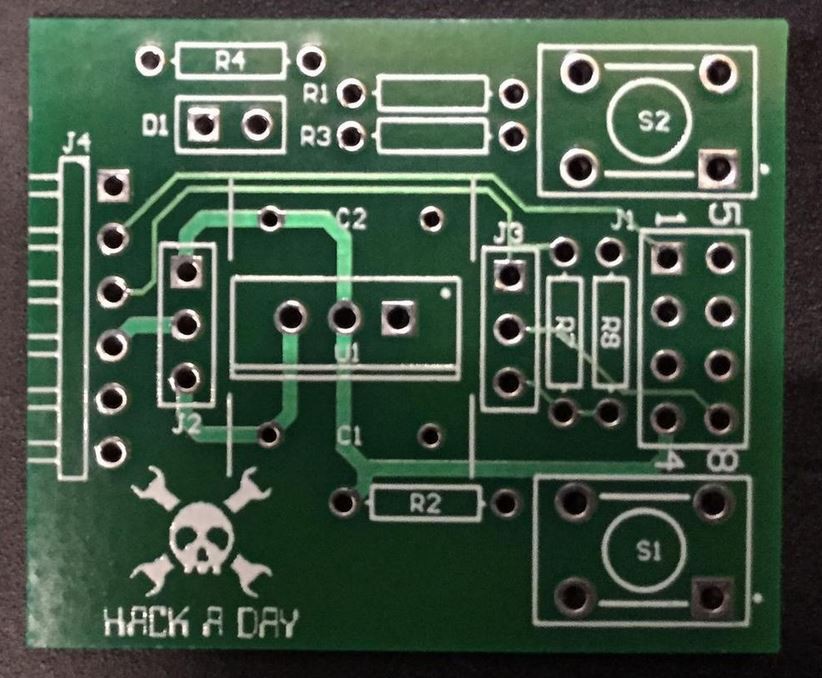
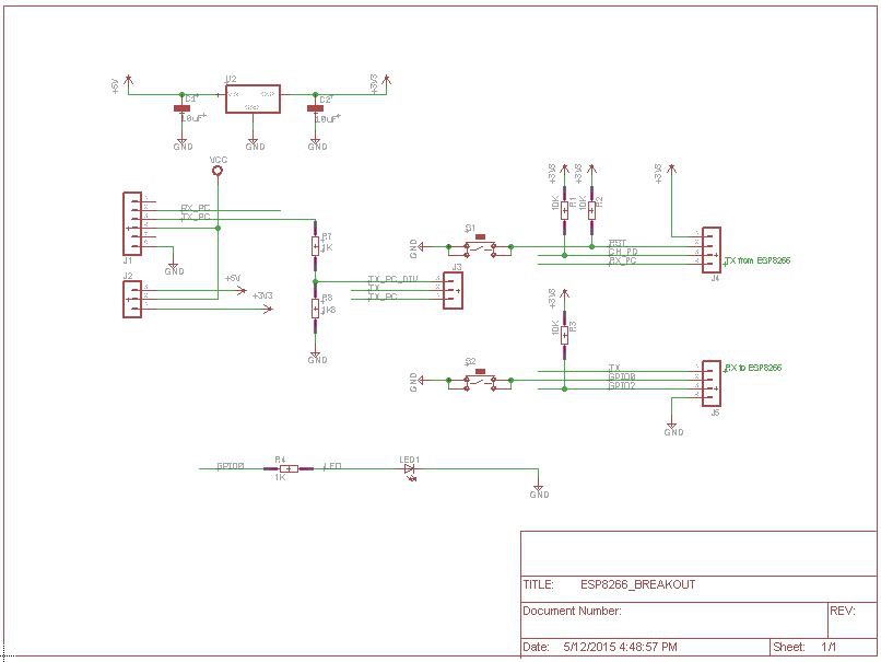
Firstly I added a regulator to provide the necessary 3V3 power when using a 5V0 input. I also added a few pushbuttons as the ESP8266 requires the GPIO0 is pulled low on startup (or low after a RESET) to put it into programming mode. The buttons on both RESET and GPIO0 provide this.
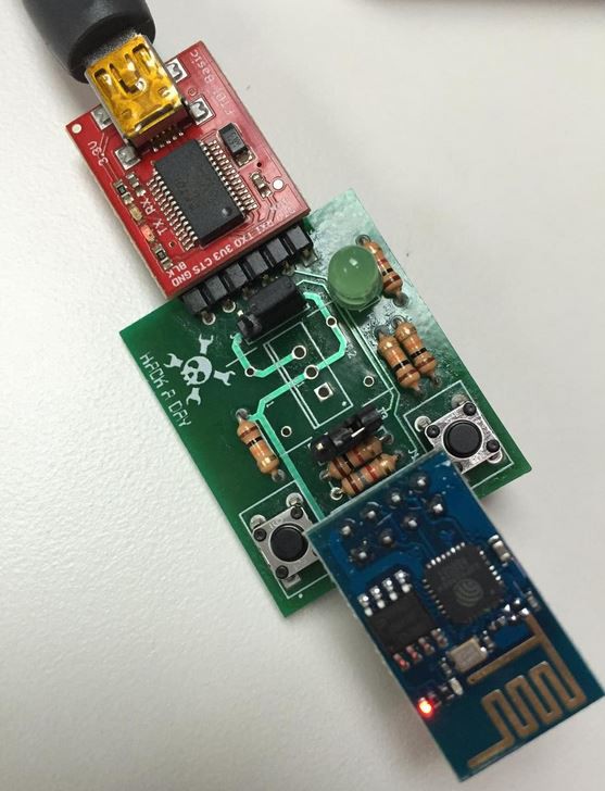
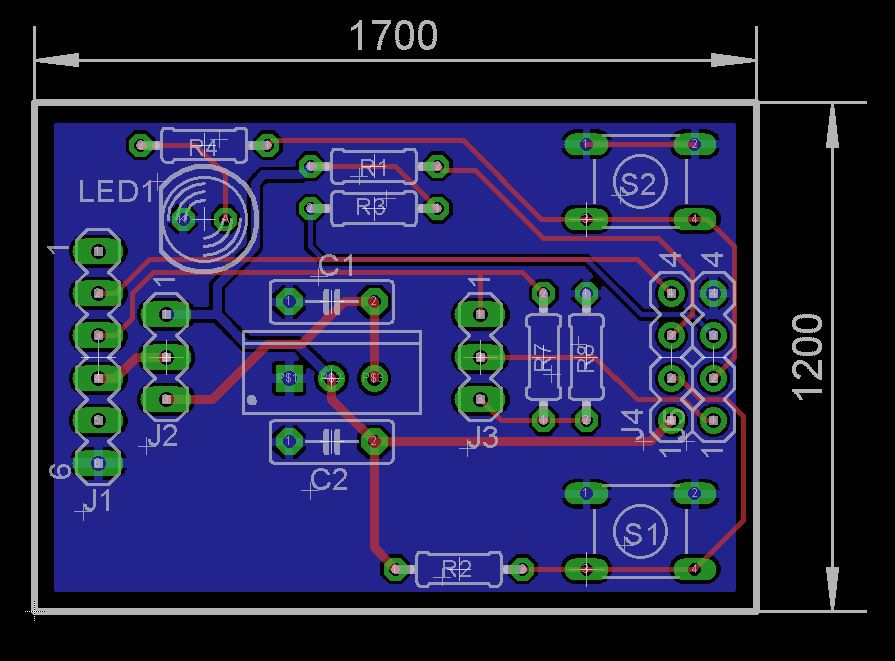
I also added an indicator LED and tried to do the whole thing thru-hole so anyone with minimal soldering skills could get in there and solder the board. The event was well received and this project includes both the design files and a copy of the powerpoint used during this event. For a complete video of the event, checkout the video below (it starts are ~17 minutes and audio is silent until then). The video takes you thru building a board in Eagle, NodeMCU and actually flashing the device in ~7hours.


 Aitor Gómez García
 RAMKUMAR R
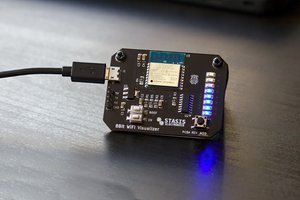
 Chandler McCowan
sweet! I'm going to fork this to use for a KiCad 101 talk at an up-coming Hackaday Prize Worldwide event in New Delhi.