 Jon Davies "Woody"
I've done almost all the prototyping and testing I think is possible to ensure everything will work well together, so I have turned my attention to getting the circuit design laid out on Stripboard. I've never settled on a particular electronics design package for my circuits, and have never done enough to warrant investing much money into purchasing one either. I recently used a free application called 'VeroDes', but this was basic and relatively old. For this project, I have turned to trying out 'Fritzing', and I must say it is a pretty good application. There are four views on the designer, laid out in the order you might be expected to progress your project. It starts with a 'Welcome' tab [for those who might need a guidance on how to get going], a 'Breadboard' tab [for those who have done this stage of prototype, and want to copy it into Fritzing], a 'Schematic' tab, a 'PCB' tab [where you can arrange your component connections and have Fritizing attempt to Autoroute], and finally there is even a 'Code' tab where you can write your code and directly upload to your Arduino or Picaxe from within Fritzing.
I mocked up the Adafruit Perma-Proto Pi HAT in the Breadboard Editor using the Stripboard object, and quickly realised I would be able to fit far less on this board than I had originally though. I did suspect I'd have to stack at least one more board on top, but it seems this will need more stacking.
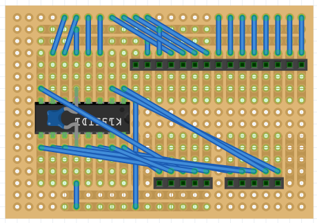
As it turns out, the stacked boards are nicely separated out into specific roles. At the bottom of the pile there is the Perma-Proto HAT, which contains the K155ID1 driver chip. The top header carries 5v, GND, 3v3 and GPIO signals. The bottom two headers carry cathode pins 0...9 in the correct order.
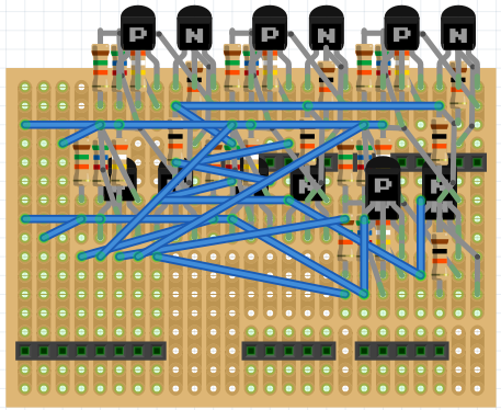
On the next level, there's the high-voltage transistors for multiplexing the Nixies and the Neons. The additional header at this level [bottom left], provides a 170v line to the high-voltage transistors, and seven multiplexed anode power outputs.
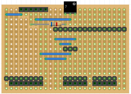
Finally, at the top level there is the power handling. The 12v & 5v PSU feeds the Pi and the HV module from here. Note: Think think I can see errors in this one, which I did fairly late last night - no surprise there are mistakes! Will be verifying connectivity on all htese board, both in Fritzing and physically! This board has an additional female header at the top left, which is where the HV module will plug in. There is also a male heade in the centre of the board, which will connect to the 12v & 5v PSU.
There is also the Display Board where the Neons and the Nixies live. I'll either use a Ribbon Cable, or just a bundle of wires to interconnect the Driver Stack to the Display Board. Not decided on which option yet.

Note that the HV Module, 12v & 5v PSU, and the Nixie Boards are not shown in these pictures, but will plug into the headers that are on the Stripboards.
Discussions
Become a Hackaday.io Member
Create an account to leave a comment. Already have an account? Log In.