The Nixie Driver IC I am going to use is a K155ID1, which is a Russian clone of the SN74141.
![]()
Using good ol' Google, I found plenty of old
Datasheets that helped me figure the (hopefully!) definitive pin-outs needed to correctly connect the IC. Together with research I'd done in an earlier log [
Figuring out the Nixie Circuit], I put together a circuit to check the logic-level signalling and the high-voltage switching.
![]()
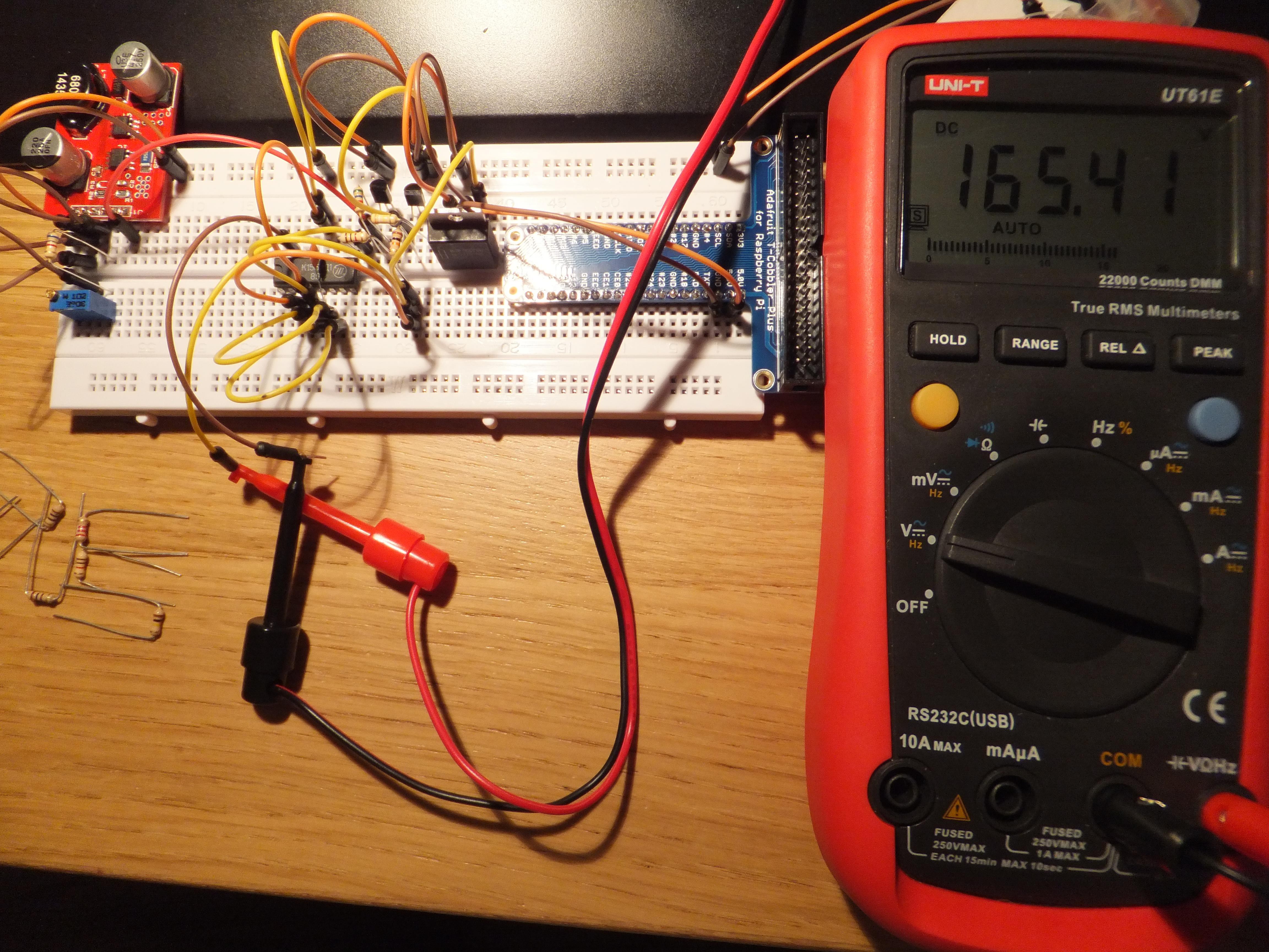
With a bit of testing and modification from the suggested schematic, e.g. R24...R29 originally shown as 0R and replaced 10M, I put together a small section using an
MPSA42,
MPSA92,
BP5275-50, the K155ID1, a small filter capacitor, resistors and jumper wires. I use a 12v power supply, and the 5v regulator gives me a 5v logic-level signal, which is good enough to test with for now. I tested a combination of binary numbers on the logic input, and probed the appropriate HV Cathode pin for 'live' voltage. Note that the pair of jumper wires, going from the 5v regulator to the T-Cobbler Plus, are doing nothing at this point.
![]()
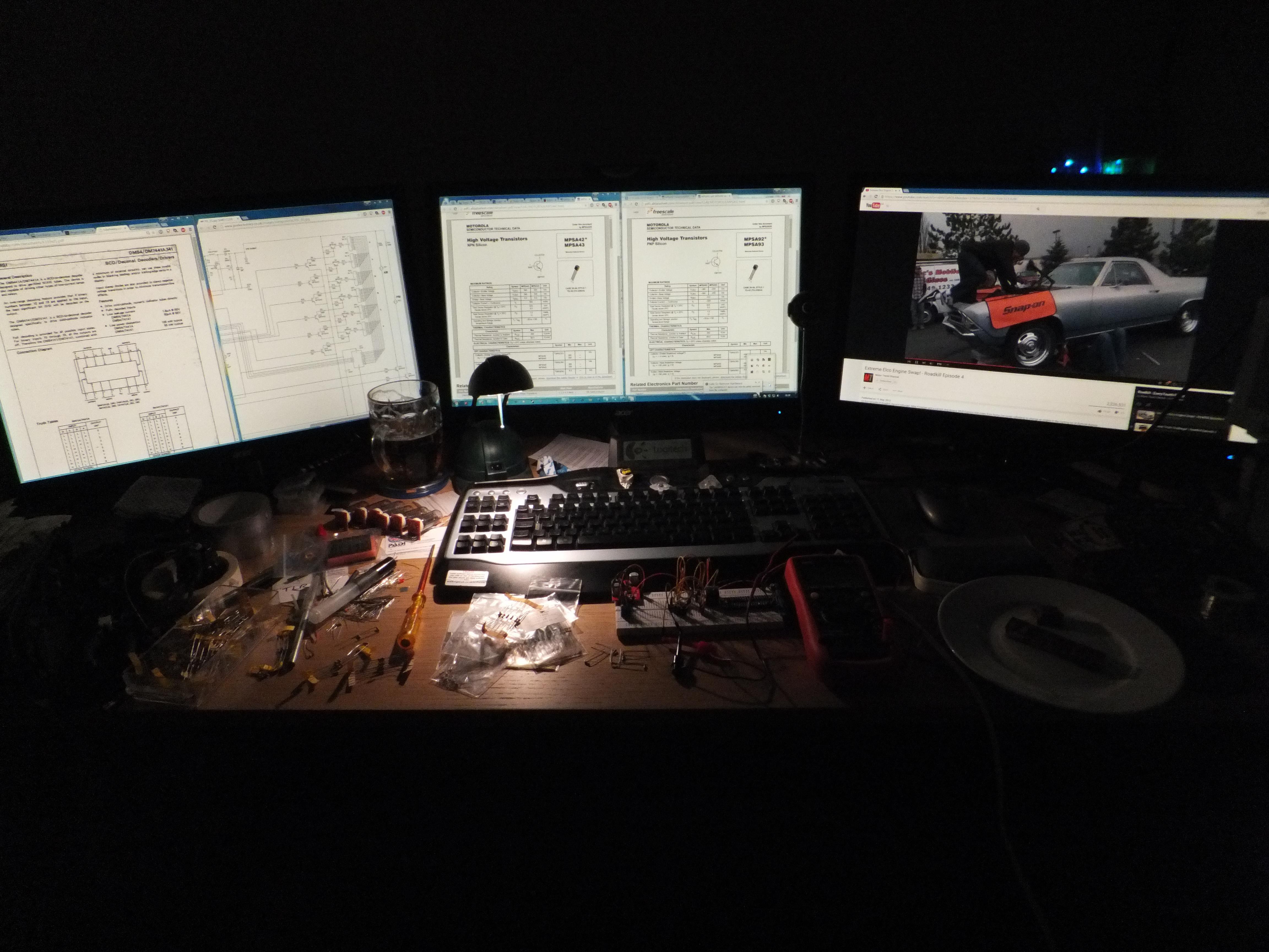
Thought I would show you a view of my rather busy desk - monitors from left to right are showing the K155ID1 datasheet [monitor 1], example Nixie circuit [monitor 1], MPSA42 and 92 datasheets [monitor 2], and most importantly, an episode of 'Road Kill' from the Motor Trend YouTube channel [monitor 3]. Key items on the desk from left to right: Pint of tasty real ale*, six IN-14 Nixies, Logitech G15, Breadboard with test circuit, Multimeter, Plate with chocolate.
*Note: Had just finished testing the circuit, it was the weekend, and I fancied a pint :) Not wise to dabble in HV when inebriated.
Note 2: Always important to have chocolate on standby for thinking and calming!
 Jon Davies "Woody"
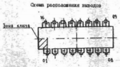
Discussions
Become a Hackaday.io Member
Create an account to leave a comment. Already have an account? Log In.