 Jon Davies "Woody"
It's time to bite the bullet and proceed with the critical stage in this project: Interfacing the Raspberry Pi's 3.3v logic with the 170v power supply in order to officially drive a few of the Nixie Tubes for the first time in this project. First step is wiring up some power for the HV Module and the Pi, and giving it a test with the multimeter. For this I am using my usual 12v PSU and stepping down to 5v using the BP5275-50.
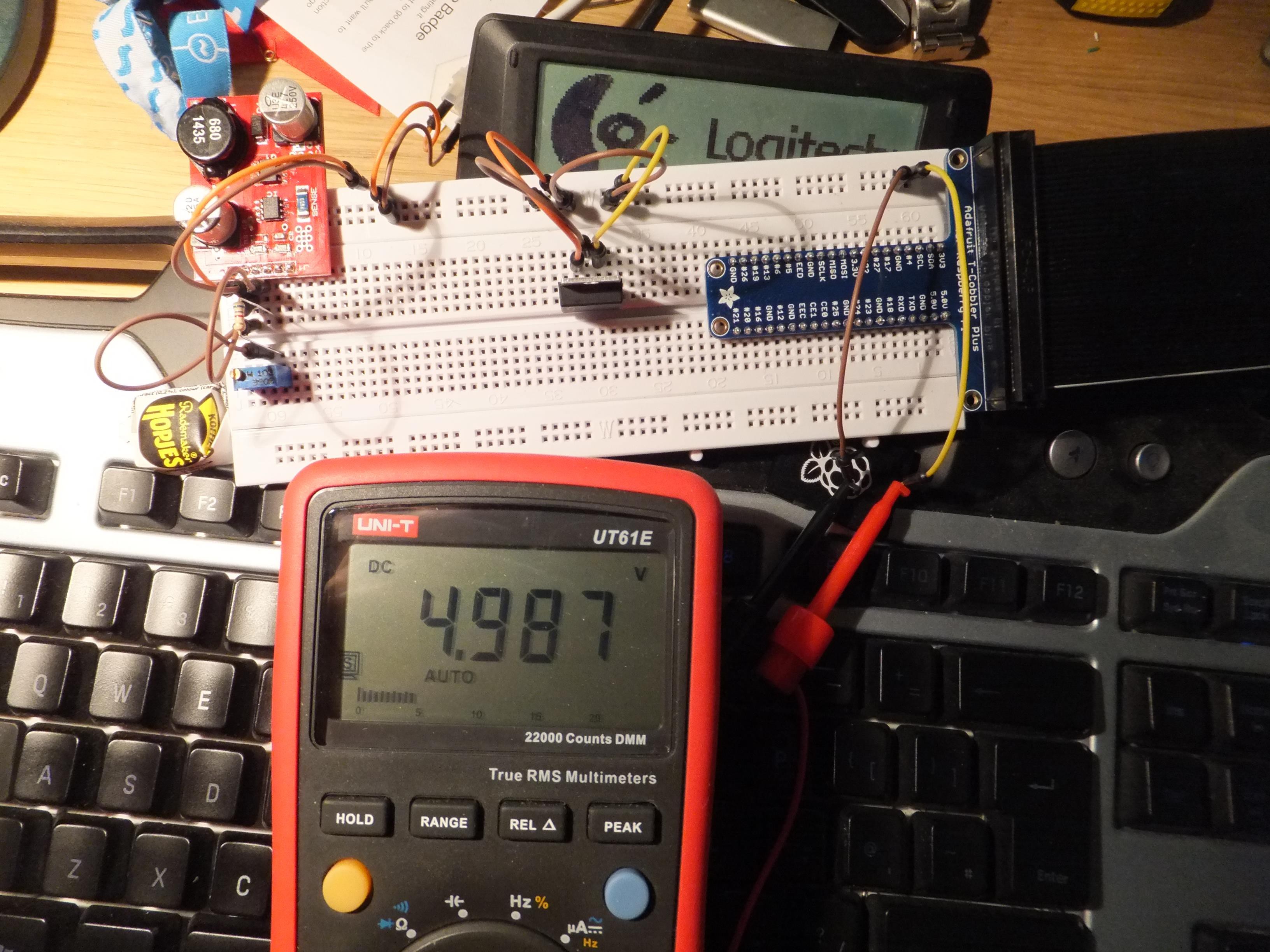
Might as well get on with trying the 5v supply to the Raspberry Pi...
After a bit of head-scratching over positioning of the components on the breadboard, I managed to get enough wired in to test four Nixies.
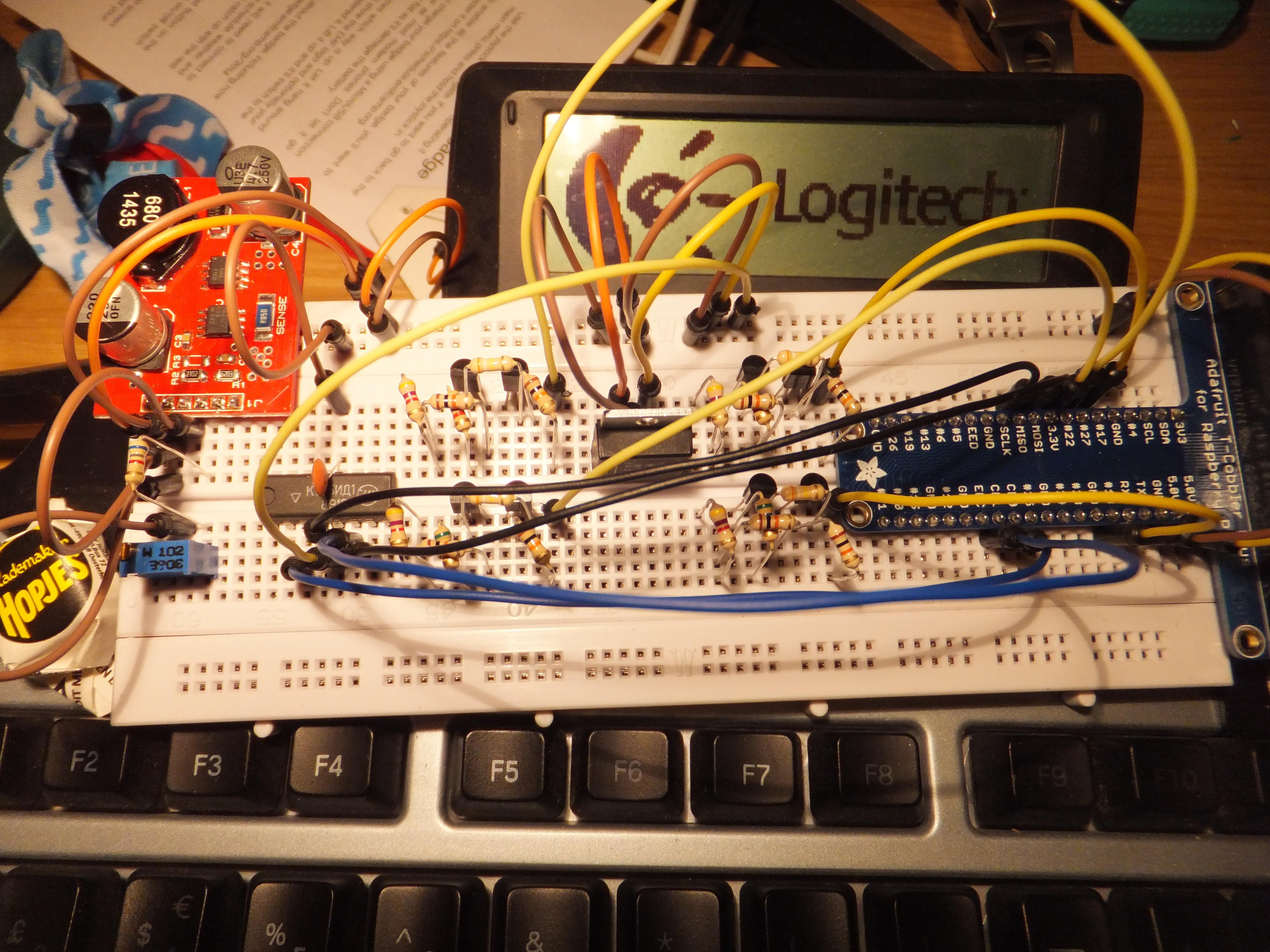
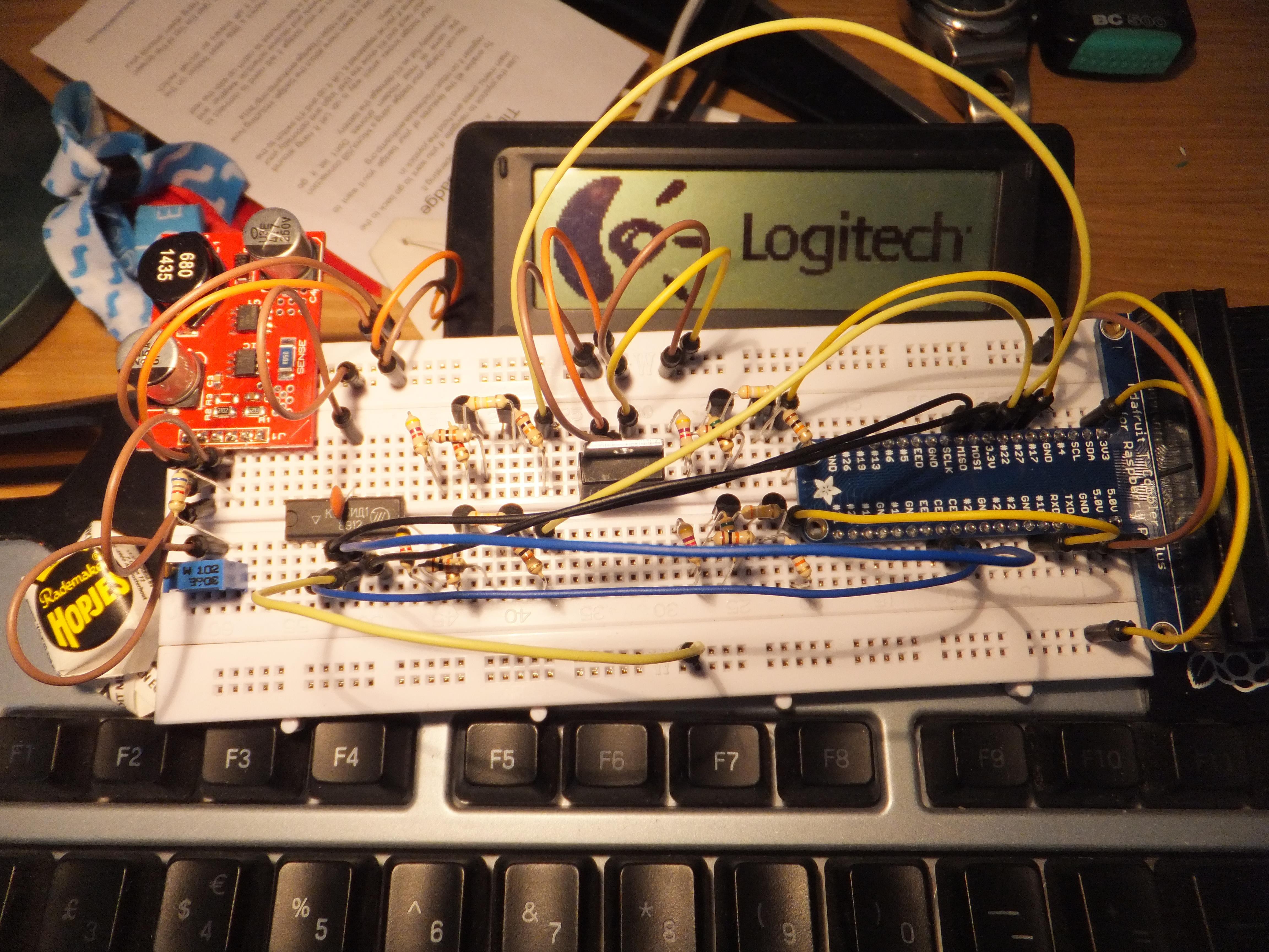
I had already video'd a test of the Pi and the K155ID1 with the incorrect 5v link to Vcc, but all seemed to go OK - no magic worky smoke escaping yet!
Update: 7th June 2015
Since the last update, I've added in the rest of the jumper wires along with a Nixie Tube, powered up the test circuit and ran the Raspberry Pi code.
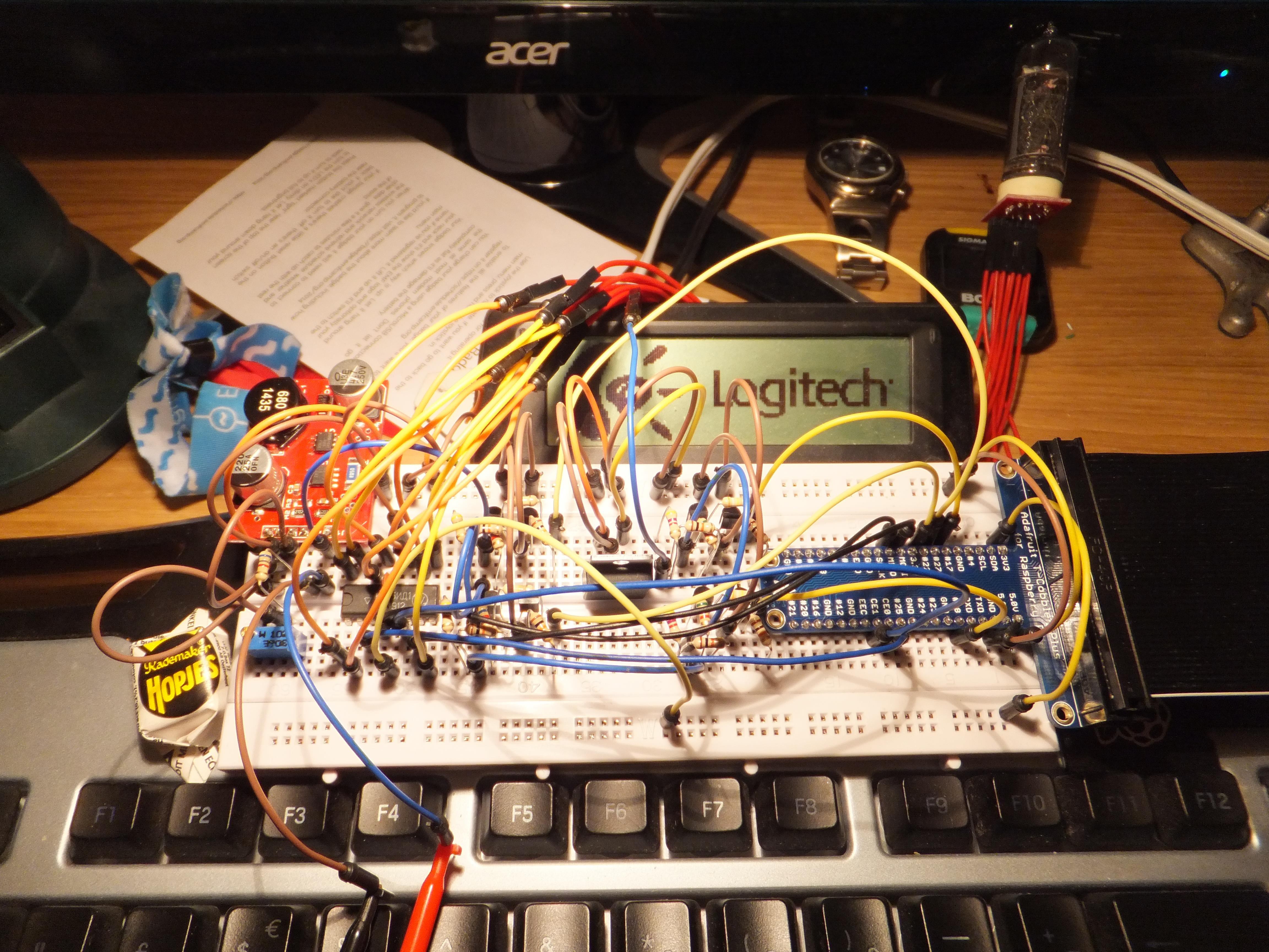
In short, the test was a success in that nothing blew up, but I did notice that I'd wired the BCD pins on the K155ID1 in the order of LSB (Least Significant Bit), but had coded the software in the order of MSB (Most Significant Bit). Easy enough to fix in either software or hardware.
Discussions
Become a Hackaday.io Member
Create an account to leave a comment. Already have an account? Log In.