 Bruce Land
Soft oscilloscope
This program:
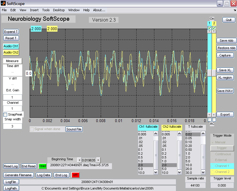
- Simulates the function and appearance of a traditional two-channel oscilloscope. The GUI consists of a simulated oscilloscope, hereafter refered to as the scope.
- Accepts real input from either the Windows sound device, a National Instruments DAQ board or other supported devices. You choose the input device when you start the program.
- Stores data in several formats that other analysis programs can use.
- Recalls stored data to perform analysis on the data
The next two sections explain how to set up the program and how to operate the controls. The program assumes that you have installed the necessary drivers supplied with whatever data aquisition card you are using. The winsound (audio port) drivers are installed with windows, but (for example) the National Instruments interfaces require NIDAQmx 8.3 drivers. This program is cycle and memory hungry. It may not work well on slow machines. The program has only been tested on machines running WindowsXP/SP2.
There are two different ways of setting up the program:
- Program Download version 24 .
The Matlab source code version requires the program and requires an
licensed, installed version of Matlab R2007a. Be sure that your Matlab
'path' includes the folder where you stored the program.
If you are not sure use the
SetPath...option in theFilemenu to investigate. - The compiled program requires three files (but NOT Matlab):
- MCRinstaller. You must accept the license on MCRinstaller use before downloading. On older machines, if the MCRinstaller fails with a cryptic error message, you may need to download some C++ stuff from Microsoft. The needed file is vcredist_x86.exe. The
.NETstuff from Microsoft may also be required, but not on most machines. - An exe which you will double-click to start the program
- This library file
- MCRinstaller. You must accept the license on MCRinstaller use before downloading. On older machines, if the MCRinstaller fails with a cryptic error message, you may need to download some C++ stuff from Microsoft. The needed file is vcredist_x86.exe. The
The scope controls:
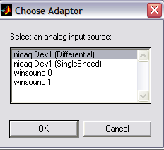
- When you start the program, you must choose an input device from
the device dialog box shown below. Some devices have more than one mode (
differential/single). Every windows machine will havewinsound0. If you cancel out of this dialog, you will get an arror message and the program will quit. Depending on which device you choose, additional controls may appear. For example, choosing the NIDAQ differential device will enable a menu calledADC input rangefor choosing the full range of the analog input. Choosing a lower range results in limited range (and potential clipping of the wavefrom), but better resolution at low amplitudes.
![]()
- Channel 1 and 2 controls are color coordinated so that all controls belonging to one channel are the same color (see below for changing the colors). Channel 1 and 2 can be turned off and on by clicking the check-boxes at the upper-right corner of the trace display. Each trace can be set to AC mode which surpresses the average trace value. This is useful for viewing small voltage changes superimposed on a large DC value. AC mode is chosen by clicking the check-boxes in the lower-right corner of the trace display. Traces may be positioned vertically by using the vertical sliders to the right of the display.
- Vertical voltage scale can be set from .001 to 10 volts full scale with
the
V fullscalecontrol, for each channel separately. Channel 1 scale and Channel 2 scale are shown at the top-left of the plot in appropriately colored boxes. - Horizontal time scale can be set from .001 second to 30 seconds with the
T fullscalecontrol. - Clicking on the
sound filebutton allows you to load a WAV file, which will be played whenever a trace is complete, if thesignal when donecheckbox is checked. For large time scales, it is nice to have the program notify you when the trace is complete. - Trigger source can be set to:
Manual, which activates the scopeTriggerbutton. Pressing theTriggerbutton will cause the scope to acquire one trace. To quit from the program or change the scope time scale, the trigger mode must beManual.Continuousto acquire data as fast...


 Bharbour
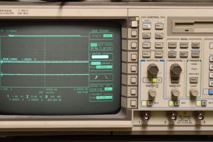
Toronto Airport Limo Service is an exclusive luxury limo service provider in Toronto, Canada that strives for excellence and quality of service with impeccable luxury class fleet and devotion to serve with perfection as a airport transport limousine service.
https://airporttransportationtoronto.com/airport-town-car-service/