 Jean-François Duval
One major reason for that is that there is a huge gap between the hardware that's used in commercial devices and in research prototypes. To make a successful robotic prosthesis you need a small, lightweight embedded system that can support high peak powers (hundreds of watts when your limb needs to push your body forward), that will be extremely safe and reliable and that will be powerful enough to run advanced controllers.
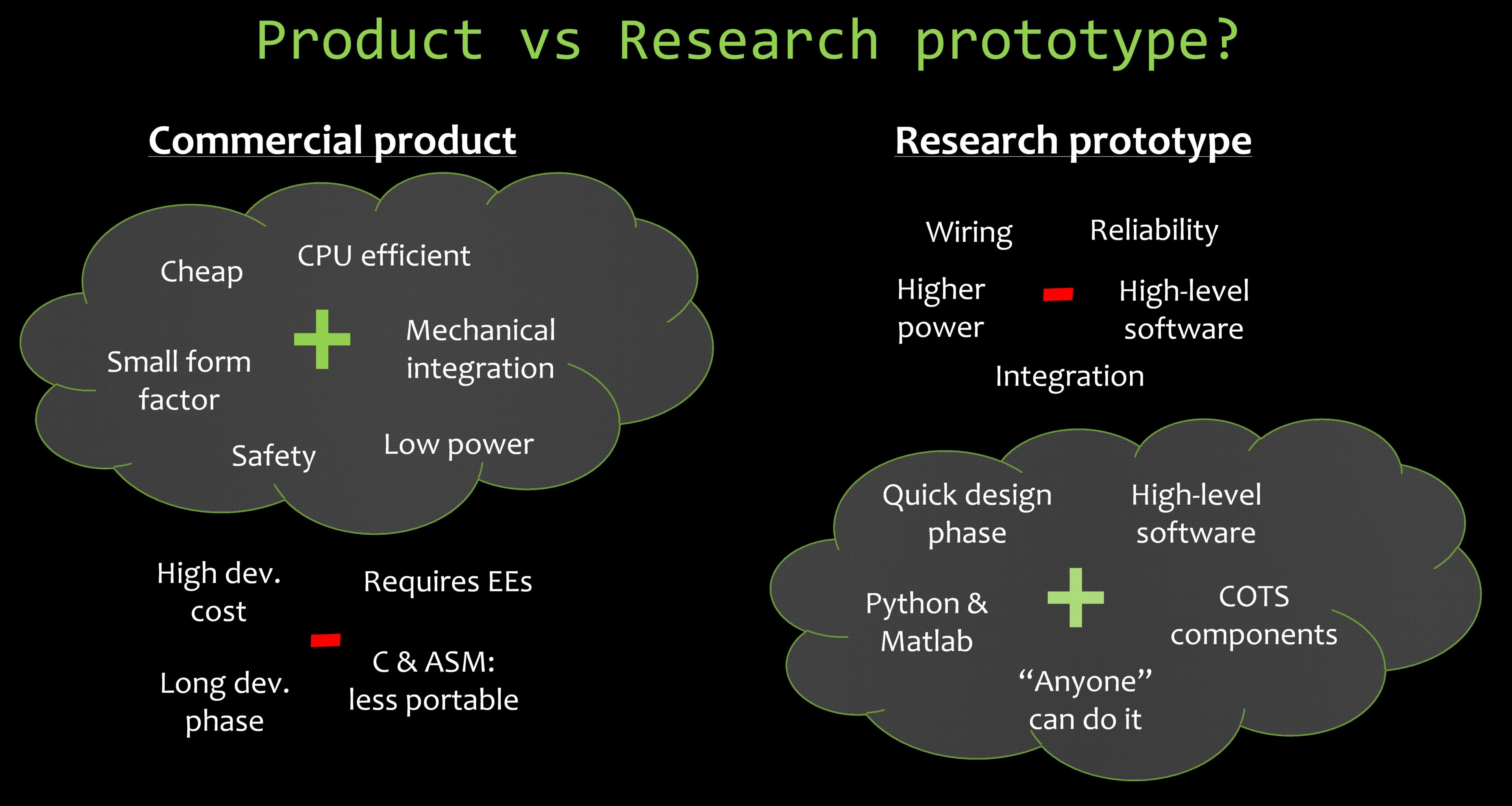
I spent the last two years solving that problem at the MIT Media Lab Biomechatronics group. The result is a kit of hardware and software that simplifies prototyping, increases reliability and safety, and frees designers from the hassle of putting together a new embedded system for every design they try. To make the world a better place, we decided to release all the plans. This means that not only university researchers, but also hackers, can use the FlexSEA toolkit to prototype ground-breaking concepts. And, as the "wearable robotic" title entails, it's not only used to replace limbs; we've also tested the system on a dual autonomous leg exoskeletons that allows its user to walk longer and/or faster.
If you only have 40s to understand the project, listen to Prof Hugh Herr explaining why it matters:
If you have 4:34, you can watch my Semifinals video, where I explain the origins of the project, show the evolution of the design, and two demonstrations (knee prosthesis and autonomous exoskeleton):
You'll find other videos listed at the bottom of this post. Keep reading for all the technical details, but if you are wondering why I took the time to explain all these portions of the project in details rather than simply pointing to my thesis, you can read the aptly named So, why am I spending all this time describing technical aspects of the project? project log.
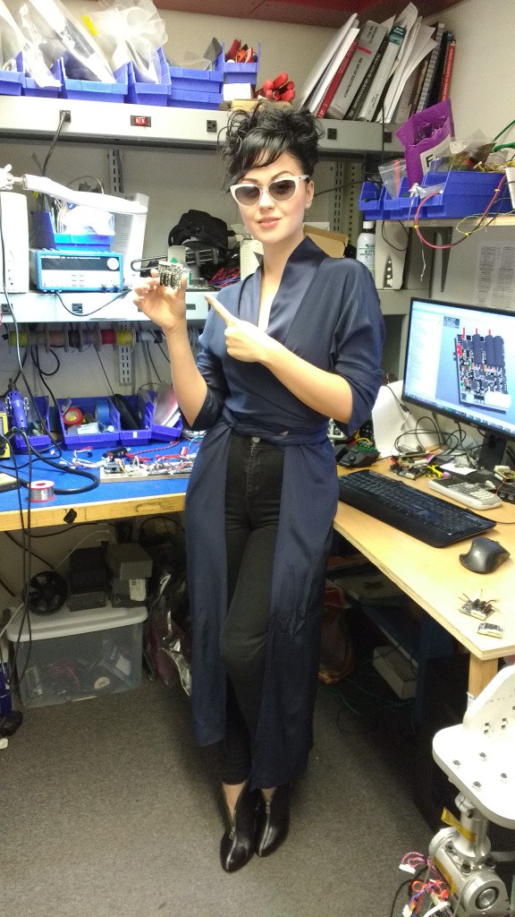
Oh, and because reading about electronics circuits can get
boring, here’s a glamorous picture of bionic pop artist and model Viktoria Modesta
showing her support for FlexSEA!
General description:
- Introduction (why do we care?)
- Design solutions – short answers
- An overview of FlexSEA
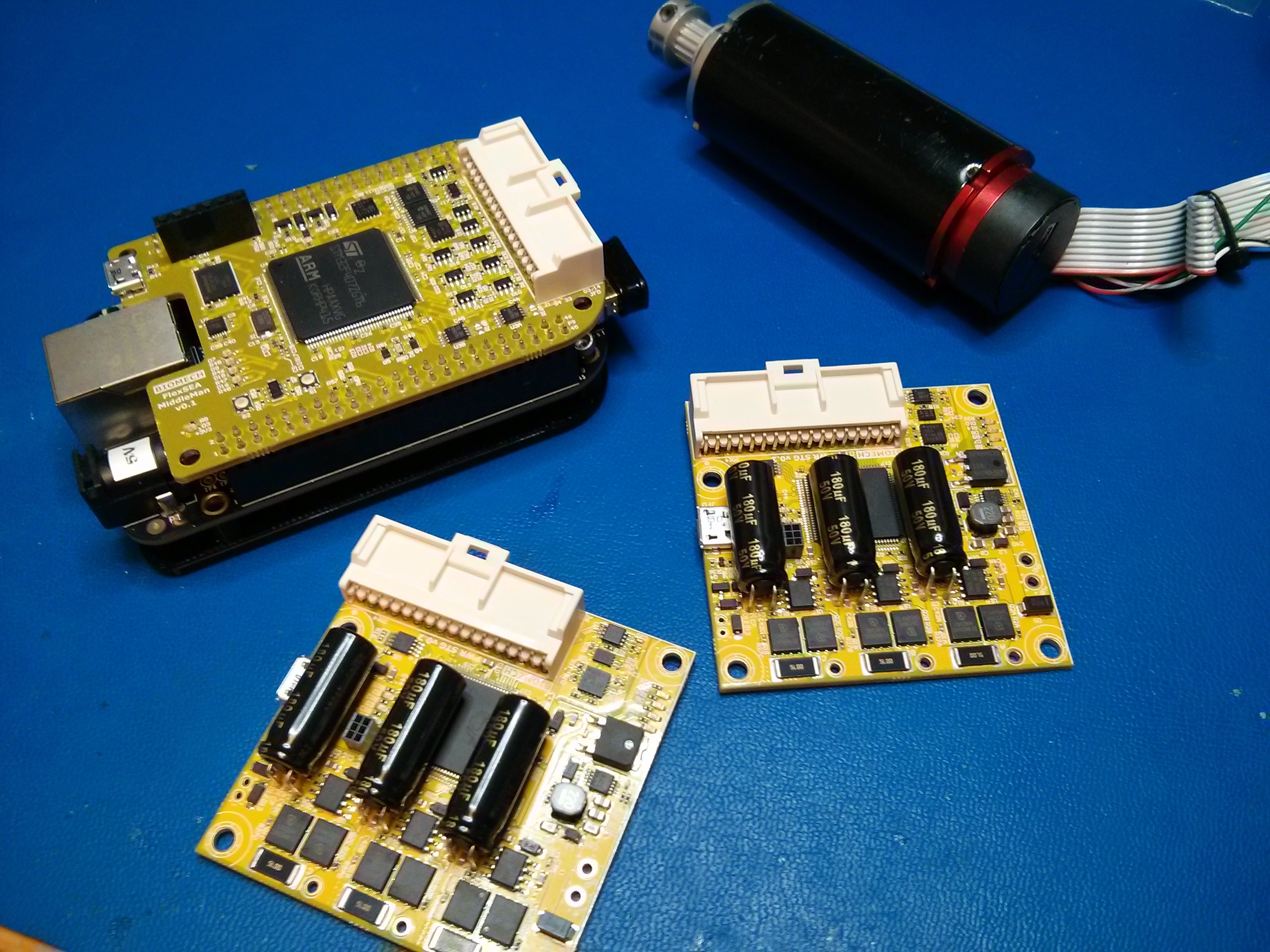
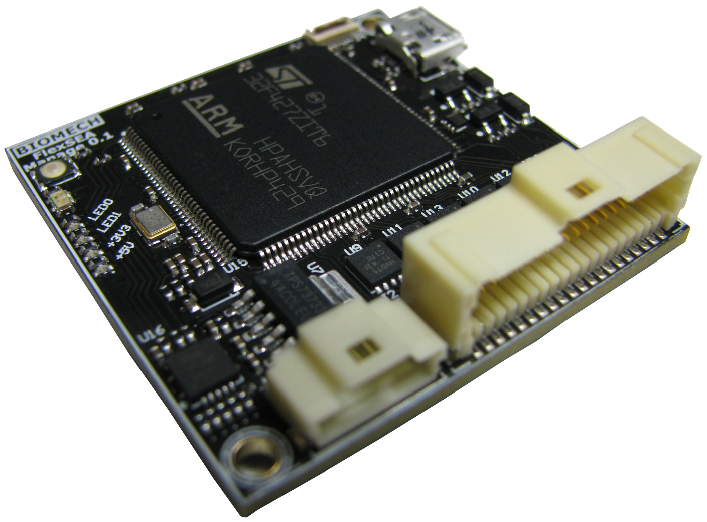
- The 3 FlexSEA boards:
- August 2015 Project Update
- September 2015 Project Update (semifinals!)
Not too technical logs, with lots of pictures:
Detailed technical description of some parts of the system:
- Controlling a brushless motor (BLDC) with a PSoC 5:
- Implementing a current controller:
- Managing timing: how to sequence tasks
- Using DMA on a PSoC
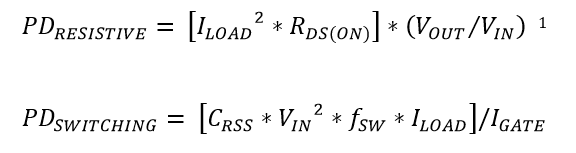
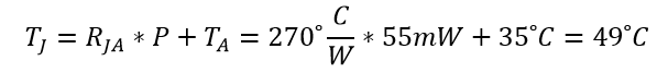
- MOSFET Power Dissipation and Temperature
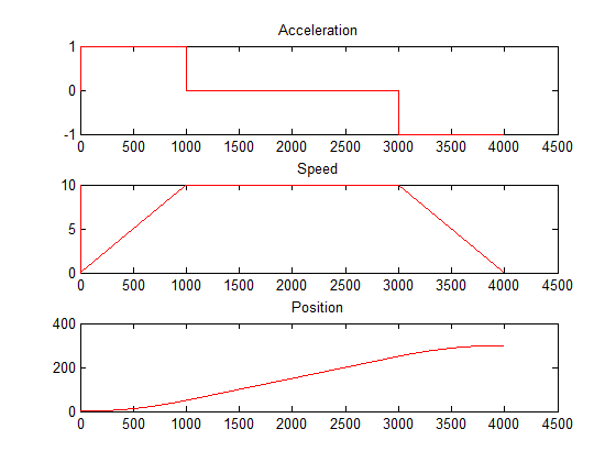
- Trajectory generation: trapezoidal speed profile
- Working toward FlexSEA-Execute 0.2
- ...
- What would you like to know? Ask in the Comments.
Videos:
- Prof. Hugh Herr talking about the FlexSEA project
- FlexSEA - Hackaday Prize Semifinals (the best video to understand the project and see demos)
- Autonomous Exoskeleton powered by FlexSEA-Execute
- Introducing FlexSEA - Hackaday Prize 2015 (keeping it for posterity, but you should skip it and watch the other videos!)
- [FlexSEA 0.1] Early bench test of two prosthetic joints (knee + ankle) (05/2014)
- [FlexSEA 0.1] Demonstrating an impedance controller (08/2014)
- [FlexSEA 0.1] Exoskeleton SG Force Controller on FlexSEA-Execute 0.1
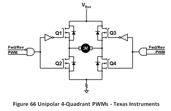

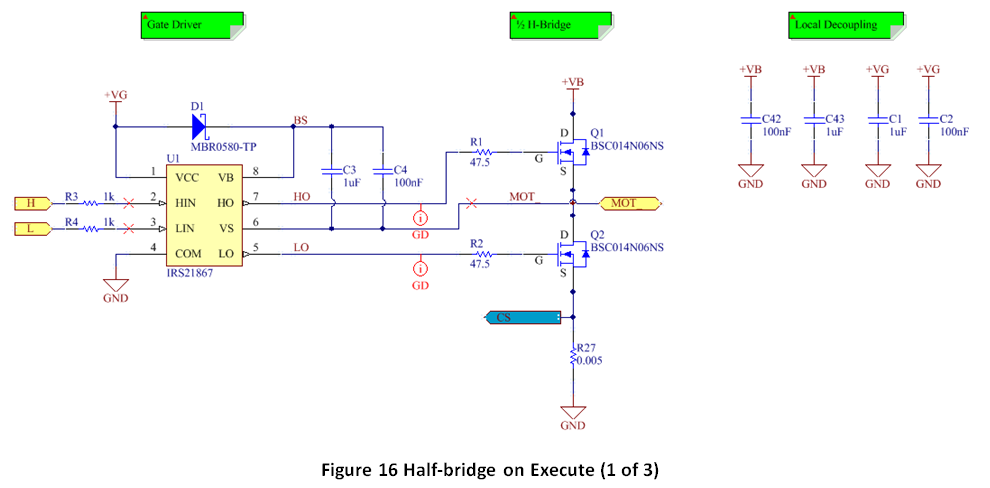
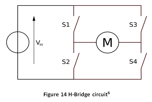 DC motors are commonly driven by a circuit called an H-Bridge. An H bridge is an electronic circuit that enables a voltage to be applied across a load in either direction. Closing S1 and S4 will make the motor turn in one direction, while closing S2 and S3 will make it rotate in the opposite direction. Closing S1 and S3, or S2 and S4, can be used to brake the motor. Closing S1 and S2, or S3 and S4, will create a short circuit on the power supply and can lead to catastrophic failure.
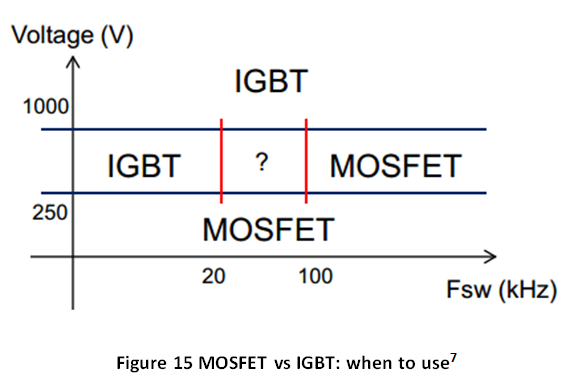


 Mark Atherton
 Alex Muir
 Phil Malone
How to buy FlexSEA? Where?