 Jean-François Duval
Motor current sensing is an important feature for motor drivers. It is used as a safety feature to turn-off the PWM when excessive current is flowing through the driver, and to control the motor torque (torque is proportional to current). In this Project Log I'll detail how I implemented a high performance current controller on FlexSEA-Execute.
The programmable analog blocks of the PSoC can be used to design a small, low-cost motor current sensor. I started by doing an LTSpice simulation of the complete analog circuit:
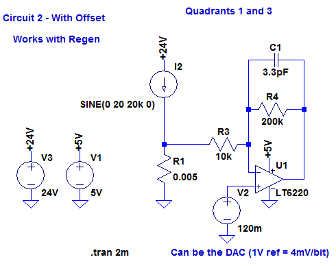
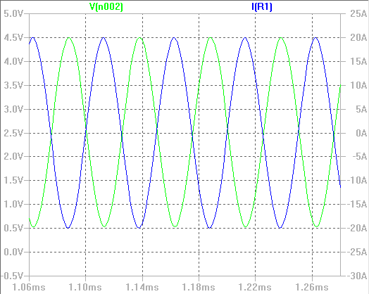
0A will give me an output of 2.5V (half my ADC voltage supply), 20A = 0.5V and -20A = 4.5V. I kept a safety margin of 0.5V near each rail to account for component tolerances and to make sure that a small overcurrent wouldn't saturate the sensor.
In the PSoC we use one operational amplifier, one DAC and one analog multiplexer. In "real hardware", we only need one shunt resistor per bridge (), two resistors and one capacitor.
In PSoC hardware, the current sensing is strongly linked to all the motor control circuits: the following schematic has a lot of components!
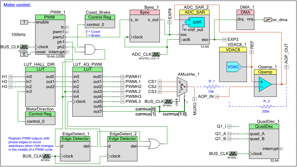
TLDR: with hardware, we amplify the current measurement, sample it at the PWM mid-point, convert it and trigger an interrupt every 5 samples.
I'll explain how the BLDC driver works in a different log; for now, let's focus on the current controller portion. PWM_1 is the 100kHz PWM signal used to control the motor speed. The pwm2 output will always go high at the mid-point of the active ON time (ie if my period is 10us and my duty-cycle is 50%, pwm will be initially off, then it will turn on at the 5us mark. pwm2 will become active at the 7.5us mark.) We use this rising edge to trigger ADC_SAR_2 (Sync_1 makes sure that the clocks are synchonized, otherwise we could miss pulses). The signal that is measured comes from Opamp_1; that's the opamp you saw on the LTSpice simulation. As you can see, an analog multiplexer (AmuxHw_1) is used to select one of the 3 sense resistors as the input of the amplifier. That selection is done in the LUT_4Q_PWM look-up table. We only read the leg that has its low-side switch turned on. Every 5th ADC sample a DMA interrupt is triggered. It calls the software current PI controller, for an effective refresh rate of 20kHz.
In Current controller: software I cover the software aspect, and show you scope screen captures.
Discussions
Become a Hackaday.io Member
Create an account to leave a comment. Already have an account? Log In.