 Jean-François Duval
Motor current sensing is an important feature for motor drivers. It is used as a safety feature to turn-off the PWM when excessive current is flowing through the driver, and to control the motor torque (torque is proportional to current). In this Project Log I'll detail how I implemented a high performance current controller on FlexSEA-Execute.
In Current controller: hardware I covered the hardware. Now that we can accurately measure current we can control it.
Every 5th ADC sample a DMA interrupt occurs. This code is called:
CY_ISR(isr_dma_Interrupt)
{
    /*  Place your Interrupt code here. */
    /* `#START isr_dma_Interrupt` */

	volatile int32 adc_sum = 0;
	volatile int32 adc_avg = 0;

	//Read last ADC value
	adc_sum = (int32)(adc_dma_array[0] + adc_dma_array[1] + adc_dma_array[2] + \
				adc_dma_array[3] + adc_dma_array[4]);
	adc_avg = (adc_sum / 5);

	ctrl.current.actual_val = (int32)(adc_avg - CURRENT_ZERO);
	//Used by the current controller, 0 centered.

	if((ctrl.active_ctrl == CTRL_CURRENT) || (ctrl.active_ctrl == CTRL_IMPEDANCE))
	{
		//Current controller
		motor_current_pid_2(ctrl.current.setpoint_val, ctrl.current.actual_val);
	}

    /* `#END` */
}
The last 5 values are averaged, and the current control function is called.
//PI Current controller #2: speed optimized
//'wanted_curr' & 'measured_curr' are centered at zero and are in the ±CURRENT_SPAN range
//The sign of 'wanted_curr' will change the rotation direction, not the polarity of the current (I have no control on this)
inline int32 motor_current_pid_2(int32 wanted_curr, int32 measured_curr)
{
	volatile int32 curr_p = 0, curr_i = 0;
	volatile int32 curr_pwm = 0;
	int32 sign = 0;
	int32 uint_wanted_curr = 0;
	int32 motor_current = 0;
	int32 shifted_measured_curr = 0;

	//Clip out of range values
	if(wanted_curr >= CURRENT_POS_LIMIT)
		wanted_curr = CURRENT_POS_LIMIT;
	if(wanted_curr <= CURRENT_NEG_LIMIT)
		wanted_curr = CURRENT_NEG_LIMIT;
	ctrl.current.setpoint_val = wanted_curr;

	//Sign extracted from wanted_curr:
	if(wanted_curr < 0)
	{
		sign = -1;
		MotorDirection_Control = 0;		//MotorDirection_Write(0);
		uint_wanted_curr = -wanted_curr;
	}
	else
	{
		sign = 1;
		MotorDirection_Control = 1;		//MotorDirection_Write(1);
		uint_wanted_curr = wanted_curr;
	}

	//At this point 'uint_wanted_curr' is always a positive value.
	//This is our setpoint.

	//From ADC value to motor current:
	shifted_measured_curr = measured_curr + CURRENT_ZERO;
	if(shifted_measured_curr <= CURRENT_ZERO)
	{
		//We are driving the motor (Q1 or Q3)
		motor_current = CURRENT_ZERO - shifted_measured_curr;
	}
	else
	{
		motor_current =  shifted_measured_curr - CURRENT_ZERO;
	}
	//ToDo above code seems complex for no valid reason

	//At this point 'motor_current' is always a positive value.
	//This is our measured value.

	//Error and integral of errors:
	ctrl.current.error = uint_wanted_curr - motor_current;					//Actual error
	ctrl.current.error_sum = ctrl.current.error_sum + ctrl.current.error;	//Cumulative error

	//Saturate cumulative error
	if(ctrl.current.error_sum >= MAX_CUMULATIVE_ERROR)
		ctrl.current.error_sum = MAX_CUMULATIVE_ERROR;
	if(ctrl.current.error_sum <= -MAX_CUMULATIVE_ERROR)
		ctrl.current.error_sum = -MAX_CUMULATIVE_ERROR;

	//Proportional term
	curr_p = (int) (ctrl.current.gain.I_KP * ctrl.current.error) / 100;
	//Integral term
	curr_i = (int)(ctrl.current.gain.I_KI * ctrl.current.error_sum) / 100;
	//Add differential term here if needed
	//In both cases we divide by 100 to get a finer gain adjustement w/ integer values.

	//Output
	curr_pwm = curr_p + curr_i;

	//Saturates PWM
	if(curr_pwm >= POS_PWM_LIMIT)
		curr_pwm = POS_PWM_LIMIT;
	if(curr_pwm <= 0)	//Should not happen
		curr_pwm = 0;

	//Apply PWM
	//motor_open_speed_2(curr_pwm, sign);
	//Integrated to avoid a function call and a double saturation:

	//Write duty cycle to PWM module (avoiding double function calls)
	curr_pwm = PWM1DC(curr_pwm);
	CY_SET_REG16(PWM_1_COMPARE1_LSB_PTR, (uint16)curr_pwm);					//PWM_1_WriteCompare1((uint16)curr_pwm);
	CY_SET_REG16(PWM_1_COMPARE2_LSB_PTR, (uint16)(PWM2DC(curr_pwm)));	//PWM_1_WriteCompare2((uint16)((curr_pwm >> 1) + 1));
	//Compare 2 can't be 0 or the ADC won't trigger => that's why I'm adding 1

	return ctrl.current.error;
}
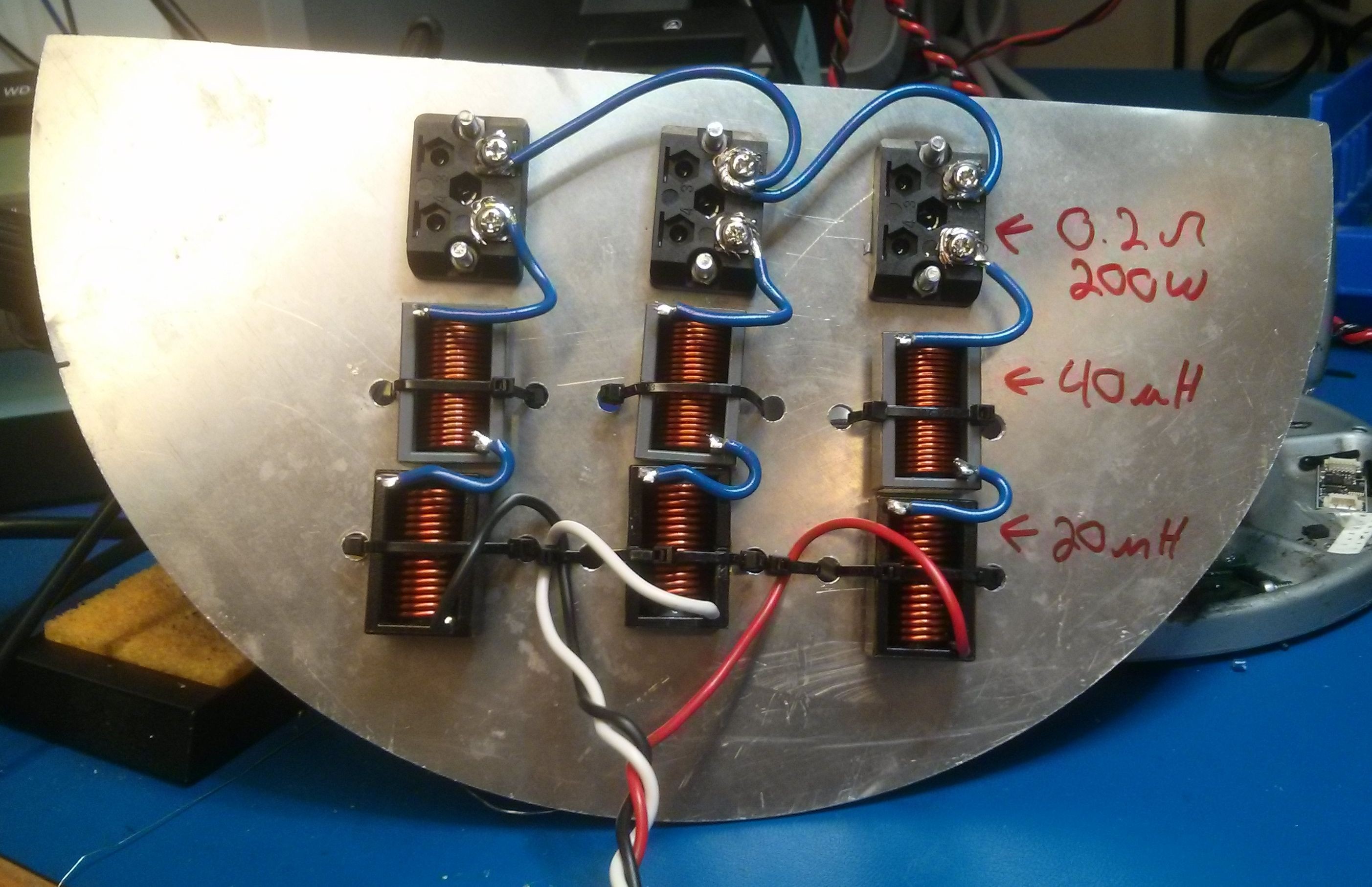
To avoid destroying expensive Maxon motors during the calibration phase a test bench was designed and assembled. In the present configuration the phase to phase specs are 120µH and 0.4Ω. The power resistors are rated for 200W. The larger inductance makes it safer for the power electronics under test. The current ripple will be half of the Maxon's.
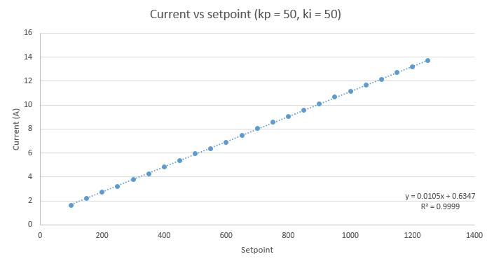
The sense resistor is 5mΩ, the analog gain is 20 and the ADC is 12bits over 5V. The theoretical current resolution is 12.2mA/bit. With a setpoint of 500, the expected current is 6.1A and the measured value is 5.94A. The absolute error is only 2.6% and the transfer function is extremely linear, great!
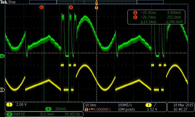
I had to make sure that the dynamics of my controller were fast enough to be used on robotic devices. To test that, I created an arbitrary waveform (a mix of triangles, sinusoids and square waves with abrupt transitions). I outputted the current controller setpoint on a DAC (yellow) and I measured the current flowing in one phase with a current probe (green). As you can see on the picture below, my current controller has no problem tracking the waveform.
Discussions
Become a Hackaday.io Member
Create an account to leave a comment. Already have an account? Log In.
Hi Andrew! Sorry for the slow response, I was on a long bicycle touring trip. You are right about the windup. In practice I don't see the problem because I'm using a trapezoidal trajectory generator to slowly update the setpoint. This is a really basic controller, I was focusing on hardware. I'm expecting contributors and lab members to write much better controllers on this plateform!
Are you sure? yes | no
Great stuff. This is going to be excellent reference for how to get a mechatronics project accomplished with the PSOC.
Note that you might have integrator windup with this controller implementation. Doing a Z transform / finite-difference-equation formulation of the PID controller can be a better approach, since you can control the history length, thus innately limit the amount of wind-up.
Are you sure? yes | no