 6502Nerd
Update June 2017
The built in language I have devised (dflat) support VDP capabilities directly such as changing colours, manipulating sprites and setting text vs graphics mode. However it doesn't have any high resolution support and that was ok when I was using the TMS9918, but now that have the TMS9918a variant which supports 256x192 bit map graphics, I thought about how I can access this.
With ROM space tight, I realised that actually I have the ability to do low level access through the commands 'setvdp', 'vpoke' and 'vpeek' - these access the VDP registers, write to VRAM and read from VRAM respectively.
So I wrote a short demo program in dflat which uses the low level access to show how high resolution bitmap graphics can be accessed. The result is in the following video:
Update end-March 2016 : short anecdote..
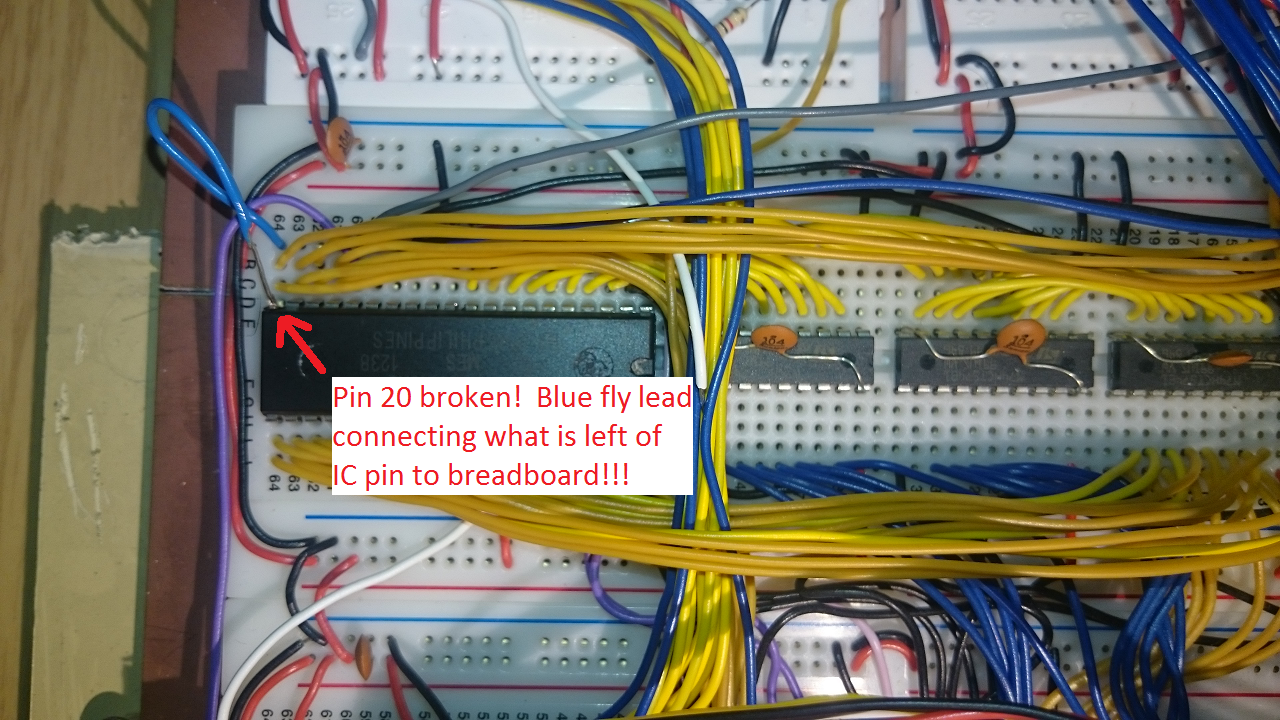
I had a little disaster with the video hardware, although it's ended (sort of ok). The hardware has been working very well for a while so I have been focussing on system and programming language software. However the last time I sat down to do some work, the video output seemed to be going haywire. I won't go through the whole story, but the root cause turned out to be my ground (!) line had broken loose from my USB header. The computer would only fire up if connected to the TV (presumably it was using the TV ground), but the video was messed up. Initially I started prodding about the VDP as breadboard connections can come loose. I pulled the VDP out once or twice in the process of troubleshooting, which is when the disaster occurred - one of the IC legs (pin 20) broke off after one too many insertions and removals. I have a TMS9928 but that doesn't give me composite colour out and I really didn't want to make up a new lead (yet). So I had to carefully solder a fly lead from the just visible connection on the IC for pin 20. See below - amazed that it worked. I think the days of this VDP are numbered and I will start making preparations to install the 9928a. The main difference is that the '28 supports RGB output - but also I am not using the 'a' variant of the 9918 so I will also have access to a full bit-mapped graphics mode.
** Update : The 9928a proved difficult to interface to a monitor with component input (not sure what I was doing wrong) - so decided to install a 9918a, which is the actual variant used on the Ti994/a and first generation MSX computers. **
As I have previously mentioned, I really needed to have video output for my homebrew that was 80s in style and capability. I poured over a number of options including:
- 6845 as per BBC Micro, Amstrad CPC
- 6847 as per Dragon 32
- Self generated as per ZX80!
The 6845 and 47 to me seemed daunting as my knowledge of digital hardware is so basic, so I discounted those.
I did a fair bit of research in to self generated video - partly inspired by Quinn Dunki's attempt using an AVR. However I didn't have an AVR so was going to use a second W65c02s running at 8MHz - I calculated that I could just about generate a 176 pixel monochrome display if I was very careful with instruction cycle counting. However, I was not sure about the ability to generate the synchronisation signals as this would need something like a 6522 or 6526 and they may not be able to keep up with the display processor. Anyway, to cut a long story short, I decided this option had too many unknowns and I could end up spending a lot of time building something which would not work or ever be expandable.
In my search I did keep going back to the TMS99xx series of Video Display Processors. These were commonly found in the TI99-4/A and MSX range of micros in the 80s, although Colecovision and other consoles also used it IIRC.
The great thing about this VDP is that it as separate video memory, which means my main computer has more to RAM to play with. Also, it has some pretty good features considering it was made in the late 70s including up to 32 sprites, 15 colours and multiple display modes (32x24 column text, 40x24 column text, 64x48 multicolour low res graphics). The 9918 (which I am using) doesn't have the bitmap graphics mode to give pixel level access to a 256x192 grid - if I want this then I could use the 9928a or source a 9918a.
However the TMS99XX series does have some pretty big draw backs. The main one is the fact it is designed to work with DRAMs, which are very hard to get hold of and very fiddly to wire up. The second at the time seemingly minor irritation was the need for a precise 10.738635Mhz crystal.
SRAM replacement for DRAM
The DRAM problem is significant because they are usually accessed very differently to SRAM. Typically an SRAM will have all the address lines required to select an address for reading or writing. A DRAM has RAS and CAS signals which select the row, and then the column - i.e. it is not done in one bus access cycle. The solution to this is something I would never have been able to figure out myself, but basically the RAS and CAS addresses need to be latched so that the full address can be assembled before sending on to the SRAM. The details about how to do this are on the web - in particular an article by Tom LeMense entitled "SRAM Replacement for TMS99x8 VRAM". A quick note about this article though - I downloaded it a few months ago fine, but searching for it now appears to need one to register with n8vem@googlegroups.com.
The implementation principles are as follows:
- Typical SRAMs have the following control lines:
- 14 (A0..A13), 15 (A0..A14) or 16 (A0..A15) address lines depending on whether the chip is 16KB, 32KB or 64KB in size. I use a 32KB chip so have lines A0..A14. However the TMS99xx will only need to assert lines A0..A13, so any additional address lines should be hardwired to ground.
- IO0..IO7 data lines, which are in input mode for write, and output mode for read depending on the three control signals below
- Chip select (CS) - active low. Only when this line is low will the SRAM accept any other control and data signals
- Write enable (WE) - active low. When this line is low, the SRAM will be in write mode (assuming CS is low). The SRAM will take data on IO0..IO7 and write it to the address on A0..A13
- Output enable (OE) - active low. When this line is low *and* WE is high the SRAM will be in read mode (assuming CS is low). The SRAM will output on IO0..IO7 the contents of the memory location defined by A0..13
- The TMS99xx is designed for DRAMs of the time, which had separate lines for read and write as well as lines for address, write, row address and column address. The signals and lines are thus:
- AD0..AD7 lines are to present, row, column and data to be written to ram
- RD0..RD7 lines to read from ram
- RAS, CAS when row and column addresses are present on AD0..AD7
- RW to indicate when data to be written is present on AD0..AD7
- A write sequence is as follows (as shown in the datasheet):
- The AD0..7 lines are first set to the row address, and the RAS line goes low to indicate the row address is valid
- The AD0..7 lines are then set to the column address, and the CAS line goes low to indicate the column address is valid (RAS stays low)
- The AD0..7 lines are then set to the data to write, and the RW line goes low to indicate the data is valid to write (CAS stays low)
- At the end of the sequence, RW goes high, then CAS then RAS.
- A read sequence is similar to above, except that the RW line stays high, and any data read from ram is presented to the RD0..RD7 lines. To enable this, wire IO0..IO7 directly to RD0..RD7.
- Two 74xx574 latches are needed to capture the AD0..7 lines during the row and column sequence, an additional 74xx574 to capture the AD0..7 for data to be written. Let's call them Latch A, B, C
- For all latches, connect the AD0..7 to the D1..8 lines, noting that the TI convention is that AD0 is the MSB and AD7 is the LSB.
- For each latch to capture data presented on its D1..8 lines, the CLK line needs to go from low to high
- For each latch to output the latched data on its Q1..8 lines, the OE line need to go low (the latch will output as long as the OE line is low).
- For latch A, which will capture the row component of the address:
- Feed the TMS99xx RAS line through a NOT gate to Latch A CLK line. The reason for the NOT is because CLK is active high whereas RAS is active low.
- Wire the Q2..8 lines to A0..A6 of the SRAM. Q1 is the MSB and not required as the TMS will output 7 lines of row and 7 lines of column address.
- Hardwire the OE line to ground, to effectively always enable this latch
- For latch B, which will capture the column component of the address:
- Feed the TMS99xx CAS line through a NOT gate to invert the signal. Then feed the inverted through *two* more NOT gates before connecting to the CLK line. This is to provide a small delay between CAS going low, and the data on AD0..AD7 being stable before being latched.
- Wire the Q2..8 lines to A7..A13 of the SRAM (the TMS doesn't use AD0 which is the MSB). Any additional SRAM address lines should be wired to ground (the TMS99xx only used 16KB i.e. 14 address lines in total)
- Hardwire the OE line to ground, to effectively always enable this latch
- For latch C (only used for write operations):
- Invert the RW line through a NOT and feed to the CLK line, to cause the latch to trigger when there is a low to high transition.
- Wire the Q1..8 lines to IO7..IO0 of the SRAM so that data to be written from the TMS99xx is presented to the SRAM. The thing to make sure here is that the wiring from AD0..AD7->D1..D8->Q1->Q8->RD0->RD7 is consistent i.e. there is a path from ADx to RDx. Also, remember this ordering when wiring up the CD0..CD7 lines to the CPU, noting that the LSB is bit 7 and the MSB is bit 0 in TI convention.
- Connect the RW line directly to the OE line so that the latch is only outputting when RW is low (i.e. when there is a write operation being done by the TMS99xx)
- This is pretty much it, except we need to make sure the SRAM is only accepting signals and doing the right operation as follows:
- Connect the SRAM OE to the inverted RW signal i.e. OE will be active low if in read mode
- Connect the SRAM WE directly to the RW signal i.e. WE will be active low in write mode
- Connect the SRAM CS directly to the CAS signal i.e. SRAM will be active once the row and column addresses have been presented.
- So simply, what all this does for a write is:
- TMS puts row address on AD0..AD7
- TMS puts RAS low
- Latch A captures AD0..AD7
- TMS puts column address on AD0..AD7
- TMS puts CAS low
- Latch B captures AD0..AD7
- TMS puts data on AD0..AD7
- TMS puts RW low
- Latch C captures AD0..AD7
- SRAM is active due to CAS being low and in write mode. Latch outputs A and B form the address and latch C output forms the data to be written
- For a read, the final three steps above are not undertaken. SRAM is active due to CAS being low and in read mode. SRAM IO0..IO7 data is output to the TMS.
TMS9918
I acquired a TMS9918 from ebay and infact also have a TMS9929a. They are almost pin compatible, with some key differences in the video output - the 9918 puts out composite whereas the 9929 puts out component video.
Some key features of the this VDP are as follows:
- The clock input consists of XTAL1 and XTAL2 - which need to be out of phase with each other and at 10.738635MHz. This is achived by feeding the 10.7Mhz clock in to a NAND gate to get the inverse. I could have used a NOT gate, but have more 74xx00 chips than 74xx04.
- The chip select lines are /CSR and /CSW. Both high means the VDP is not selected. Only one of /CSR or /CSW can be low at any time. This is achieved by feeding the IO2 output of the decoder and the 6502 R/W line through NAND gates to get the required select states.
- The MODE line selects command or data access to the VDP. As the 6502 is memory mapped, the A0 line is used to select MODE. The effect of this is that the 6502 selects the VDP by accessing memory locationd 0xB400 and 0xB401
There are a number of other small quirks and considerations, but the above are the main ones, aside from the SRAM circuitry, which also complex (for my brain), is still less cumbersome than using DRAMs.
Discussions
Become a Hackaday.io Member
Create an account to leave a comment. Already have an account? Log In.
Thanks for the reply.
See link below which clearly shows the issue. Space invader pattern is correct colour - but the eyes should be Red!
I was starting to come to the same conclusion that it was working.... Now I know exactly what they mean re "Never the same Color".
I initially planned to use the 9929. However after looking at the additional circuitry required to drive the output I decided to go with the 9918a.
I already have 2 x 9929s so a little project for me over the next few weeks!
http://www.kevcoop.info/output.jpg
Plus a link showing the CPU / RAM / ROM board + Video Board.
http://www.kevcoop.info/kh-1.jpg
Thanks again
Are you sure? yes | no
Yes looks like my output, so it's working fine - we'll just have to live with it!
One thought is to check the 10.738Mhz signal - is it stable and close as possible to the TI spec. I'm sure it must be pretty good else the TV would not lock on to the signal..
By the way - SWEET project :-)
Tell me more about this - what speed 65c02, what is the software stack, what other plans??? :-)
Are you sure? yes | no
Thanks for your help on this. very much appreciated.
Current Hardware
Currently I have the 65c02 running @2Mhz. I have also successfully tested with an off-board clock running at 4Mhz and it runs ok - but not fully tested.
CPU 65c02
ACIA R6551 or WDC65C51 (
ROM 32K
RAM 32K (Minus 256 bytes for I/O - decoded to 16 I/O ports! )
SOUND - AY-8910 (x 2 ) - Not sure why I went for two ! possibly just filling up space on the PCB!
3 x 65C22 for IO (One will be used for the AY-8910)
Initially I built all this on a Breadboard (or two) - but hit a lot of stability issues. I then decided to get a PCB made - best decision I made - all very stable now.
Once I have a work computer (including sound + graphics) I will then look to reduce the chip count / PCB size and try to build on a single PCB.
Software Stack
Pure 65c02 assembler (Currently using Retro assembler)
Long term plan is to write my own assembler for it. But still learning 65c02 assembly !
No plans to run BASIC !
Also plan to write a few games in 65c02 assembler i.e. Pong (any 6502 / z80 based computer should have a version of Pong), Invaders, Pac-Man etc.
Short term plans
1. Re-Visit the VDP - possibly the 9929 or V9958 - not sure I can live with those colours !
2. Document the project online - possibly via github.
Are you sure? yes | no
I've built a 65c02 based computer and I'm currently trying to get the TMS9918A working. I've connected the VDP as per the "SRAM Replacement for TMS99x8" document. I've now managed to populate the pattern table, colour table and name table with some test data and do see a display on the screen that matches the patterns I'm expecting. However, the main issue at the moment is with the colours. i.e. If I draw an horizontal line on the screen this comes out in the expected colour. However, if I then draw a number of vertical lines they alternate between 3 colours (not always the same 3) across the screen. I've checked and double checked the setup and can't find any issues with my wiring. I've also re-checked the colour table and the values stored for the vertical lines are identical to the values for the horizonal lines.
I've tried on 3 different Samsung LCD TVs (I'm based on the UK) and they all show the same issue with the vertical colours.
Do you see anything similar during the development of your 6502 based computer.?
Any ideas what the issue could be ? Things to check ?
I've also tried 3 other TMS9918a chips and the display is identical .
Are you sure? yes | no
Hi
Firstly sorry for the delay - I didn't realise I get Log level messages which don't show up unless I actually to the the log.. hence I missed your noted from earlier in the year.
I think on this point, looks like it is working to me! The reason you get horizontal lines fine but vertical lines not the right colour is simply that the composite output is not the best for vertical lines.
I can try and get a picture at some point and put it up on here - but it's a common problem as the NTSC signal (per your first question in September) is well known for poor colour.. didn't people jokingly say NTSC meant 'Never The Same Color'?!
The alternative is getting a 9928 or 9929 - I think these have component output. I have one of these but I could never get the output to display in colour, ironically - although the picture was noticeably cleaner even in B&W that composite out on the 9918a.
So just something to live with unless you really want to try for a 9928/29..
Hope that helps and assures you that you do have a working set up - congrats by the way :-)
Cheers!
Are you sure? yes | no
Hi
I see you are located in the UK. What type of TV have you connected your computer to via the TMS9918A ?
My understanding is that the TMS918A outputs a composite NTSC signal. Is your TV a NTSC model ?
From what I've read most modern LCD TVs support NTSC / PAL - Is this correct / your understanding?
Thanks
Are you sure? yes | no
This is a very interesting project!
Have you coded any demos for the TMS? Like bouncing sprites around? Typically, the TMS was used with Z80 CPU's so most of the demos I find are for that. Would be real interesting to see some demos for 6502.
On the crystals, Mouser has them in stock. But I'm not sure what it would cost to ship them to the UK.
Are you sure? yes | no
Hi - thanks for the encouragement!
So I haven't coded any demo for the TMS yet - the snaps I took show a few sprites in the shape of basic space invaders just to make sure I have got control over the TMS. Yes aside from the TI99/4 the TMS was often used in Z80 machines, of which the MSX machines were most popular. I am currently constructing the built-in interpreter (dflat) which is progressing well and my thought is that I will add sound and graphics commands to this and use that to demo the whole thing with a simple game. It will not really be pushing the TMS doing this, so a future project will be to do a pure 6502 assembly demo. Without starting Z80 vs 6502 debates (!), my gut feeling is that the 6502 should be able to push the TMS harder due to the higher memory bandwidth that the 6502 has on a cycle for cycle basis compared to the Z80.
I did see that Mouser has the crystals but they want quite a lot for shipping - will wait until I need a few more bits as shipping cost will then be justifiable.
Are you sure? yes | no
Where do you live? I might be able to send you a crystal. Or perhaps you could get some from eBay. I buy a ton of stuff from China (via eBay) and much of the time the shipping is free. Takes a month to get here but oh well.
Not to pimp my own repo's, but I have assembled a couple GitHub repo's with the intention of gathering documents for the TMS9918 and various audio chips from the era.
Might be useful in your research.
https://github.com/cbmeeks/RetroAudio
https://github.com/cbmeeks/TMS9918
Are you sure? yes | no
I'm in the UK hence the shipping issues from Mouser. But yes I guess I could source from China and wait a month - I'm not in a desperate rush as the clock circuitry is working well with a stable picture and colour. Thanks for the offer to send me direct, if I have no luck in my search then I will come back to you on that!
No worries pimping your repos! I had a look through and thanks for adding my link to the video repo. I also noticed your sound repo - have you seen that I am actually using a General Instruments part in my computer? Here's another link to add to your collection!
https://hackaday.io/project/5789-6502-homebrew-computer/log/19481-sound
Have you got a project on the go too?
Are you sure? yes | no
Could you please provide additional information on the "SRAM replacement for DRAM" procedure? It looks like the original document remains unavailable. Thanks.
Are you sure? yes | no
Hi. Bear with me - I will try and document what my circuit is doing. But check your parts bin - you will need 3 x 74xx574 and 1 x 74xx04 to connect the TMS99xx to an SRAM unit. Once I write it down, it will hopefully be good enough for you to build from. Will try and come back to you over the weekend.
Are you sure? yes | no
Hi. I've updated the body of this blog to explain the principles of using SRAM with the TMS99xx. I hope it is detailed enough for you to understand it and be able to wire up your own solution - best of luck!
Are you sure? yes | no
Thanks a lot. Your instructions are quite clear and I should be able to implement this as soon as my TMS9918A arrives. However, there seems to be a couple of issues:
1) For latch B, "Wire the Q1..8 lines to A8..A13 of the SRAM" would imply wiring 8 pins from the latch to just 6 pins of the RAM.
2) For latch A: "Wire the Q1..8 lines to A0..A7 of the SRAM" would imply wiring 8 pins, but 7 pins should suffice for a 16K address space.
Looks like it should be: Q2..8 from latch A to A0..6 of the RAM and Q2..8 from latch B to A7..13 of the RAM. Leaving both Q1 pins NC. Is that correct?
Are you sure? yes | no
Hi. Ooh, you're right. I wasn't thinking properly when I wrote this up - so yes the TI only uses 7 bits for row and column so only the least significant AD bits (i.e. AD1..AD7) for Latch A and B are useful hence connect D2..D8 to A0..A6 in Latch A and D2..D8 to A7..A13 in Latch B. That was pretty observant - sounds like you will have no trouble in getting this working. Let me know how you get on and publish your creation!
Are you sure? yes | no
Hi. I couldn't source a 10.73865MHz crystal so that wasn't an option for me. But I did have a crystal with twice the frequency - 21.47727MHz, so used that and used a 74xx161 counter to divide down for the VDP (to get 10.73865, plus a 74xx00 to get a clock inverse) and the CPU (to get 2.68). The CPU would easily run at 5.37MHz but the 6526 CIAs won't keep up as they are 2MHz parts (although they seem to run ok at 2.68MHz). If I can source the right crystal, I will use that for the VDP - the current set up works ok, but the picture quality is a bit ragged. 21MHz signals running across multiple breadboards and long wires I guess are affected by loads of stray capacitance which affects the clock signal quality.
Do you know where to source 10.738MHz crystals? I'm UK based..
Are you sure? yes | no
You mentioned that you needed additional clock circuitry to get this to work. The datasheet does not mention this. The typical application circuit shows that you can just wire up a crystal across these two pins with capacitors to ground. Did this not work for you?
Edit: I am not getting any signs of life out of the chip. I expected there to be clock signals at pin 38 and 37, but I ain't getting any. Please tell me if you see those signals. I only wired up the power, reset and crystal.
Are you sure? yes | no