 6502Nerd
Latest Update - Optimising SD Card send and get byte routines
I have been tinkering with the SD card low level routines. It was bugging me that when I wired up the SD card pins, the MISO line was attached to pin 2 Port B of one of my VIAs. MISO stands for Master In Slave Out - i.e. the output from the card, which needs sampling bit by bit to retrieve data serially. In addition the output from my machine to the card (MOSI - Master Out Slave In) was coded rather hamfistedly.So I resolved to eliminate this worm in my brain this morning. I swapped the MISO line to pin 7 and moved the CLK line to pin 7. So what? Well know when I read the Port B register, I don't need to do a bit test for the MISO state - the N bit of the 6502 will be automatically set. So I can use this feature to optimise the code.
Here is the new code to get a byte. The inner loop which is called for each bit is a maximum of 29 clock cycles. The previous code (see further down in this log) is a maximum of 37 clock cycles. So 8 clock cycles per bit doesn't sound like much but this routine is used constantly when reading or writing from the SD Card. The clever bit is the CMP - this is used to do a test subtraction which will set or clear the carry flag which can be used to directly shift in the correct bit without cumberson bitwise tests or operations.
sd_getbyte
	phy

	lda SD_REG
	ora #SD_MOSI			; Set MOSI high
	sta SD_REG

	ldy #8				; Shift in the 8 bits
sd_shiftinbit
	ora #SD_CLK			; Toggle clock line
	sta SD_REG			; Low->High
	lda SD_REG			; Sample SD card lines (MISO is the MSB)
	eor #SD_CLK			; Toggle clock low
	sta SD_REG			; High->Low
	cmp #SD_MISO			; Trial subtract A-MISO, C=1 if A >= MISO else C=0
	rol tmp_a			; Rotate carry state in to tmp_a
	dey				; Next bit
	bne sd_shiftinbit

	lda tmp_a			; Return response in A

	ply

	rts
Here is the new code to send a byte. The inner loop here is 33 clock cycles, the previous code (see old entry further down) is 38 clock cycles. Only 5 clocks per bit - but 8 bits per byte, so 40 clocks saved per byte to send. Sending 10,000 byte saves 400,000 clock cycles which @ 2.68Mhz is 0.15 seconds saved.
sd_sendbyte
	pha
	phy

	sta tmp_a		; For shifting out
	ldy #8			; 8 bits to shift out
	lda SD_REG		; Load the SD register to A
sd_shiftoutbit
	ora #SD_MOSI	        ; And initially set output bit to '1'
	asl tmp_a		; Unless the bit to transmit is '0'
	bcs sd_shiftskiplo	; so then EOR the bit back to 0
	eor #SD_MOSI
sd_shiftskiplo
	sta SD_REG		; Save data bit first, it seems, before clocking

	ora #SD_CLK		; Set CLK bit
	sta SD_REG
	eor #SD_CLK		; Reset CLK bit
	sta SD_REG

	dey								; Count bits
	bne sd_shiftoutbit				; Until no more bits to send

	ply
	pla

	rts
I did some hand timings of saving a large dflat program (Tetris), which is almost 15,000 bytes of code. Using the old routines, the time to save was an average of 8.5 seconds. Using the new routines which take advantage of the rewired MISO line, the average is 7.9 seconds. So I am pleased with this :-)
***************
I have got my head around FAT16 well enough for basic file handling. The system can now:
- DIR : Perform a directory listing, showing only files (not anything with special attributes, and ignores Long File Names)
- Open : Equivalent of the MSDOS 'Type' command - outputs a file to the screen / terminal. I've tested this with 200KB+ files, which shows that the software is correctly iterating through multiple SD card sectors as well as FAT16 clusters.
- Save : Saves a region of memory under a filename. This shows the software can correctly fine space in the directory table as well as cluster tables to create a new file
- Del : Deletes a file, which requires marking the file entry in the directory table and then updating the cluster table to mark all used clusters as free
The good thing about FAT16 of course is that I can transfer files between my homebrew and PC. This means I can assemble a binary on the laptop and then copy it to SD card for loading and running on the homebrew.
The FAT16 handling has eaten almost 2KB of ROM, which is a lot. But now that I have file handling, I could start moving things out of ROM and on to SD card. The most obvious thought is to offload the font definition data to SD, which will save 1KB. This data is only used on start up to initialise the TMS9918 and then doesn't get used again - so reading from SD card although slow is no big deal.
*************
Ok so for my homebrew to be getting towards being a self-contained computer, I need to add some mass storage capability. I already have a serial interface to PC and I suppose I could have built some software to save and load through this channel - but in the end I was interested in learning how to build my own SD interface and drive it.
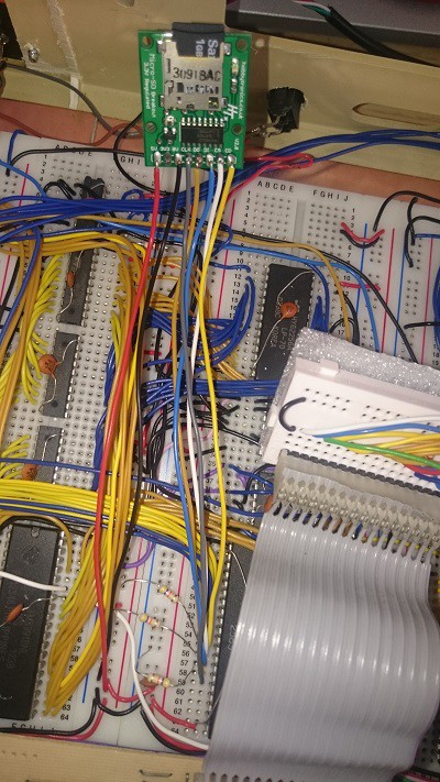
First thing I note is that all SD cards run at a lower voltage, typically 3.3V. My hardware is all orientated around 5V, so started looking in to a simple voltage conversion approach. But in the end I decided to purchase a cheap breakout board with built in voltage regulation and the SD card slot. Hobbytronics (www.hobbytronics.co.uk) sell one for very little money. I felt like I was cheating a bit, but all the breakout board does is provide 5V to 3.3V conversion, a physical slot to place a micro SD card, and the basic signals (see below).
So how to drive an SD card interface? Well the basic signals for SPIO mode are as follows:
- CS (Chip Select) - Output. Drive this line low to select the SD card
- CLK (Clock) - Output. Drive this line high and low for each clock pulse to enable synchronous transmission of data
- DO (Data Out) - Output. Drive this line to transmit data to the card. Also known as MOSI (Master Out Slave In)
- DI (Data In) - Input. Sample this line to receive data from the card. Also known as MISO (Master In Slave Out)
There is also a CD (Card detect) line, which I have wired but not decided to make use of at this time.
So these 5 lines (including CD) are connected to spare lines on Port B of the second 6522 VIA. Of course the DDR register needs to be set appropriately to be either output or input - here only DI and CD are input.
So the hardware side of things seemed reasonably straightforward, so now I had to understand the SD protocol and how to drive the card through software in 6502 assembly. This took a lot more time than I thought.
I hadn't really thought about it, but basically every SD card is a memory array (NAND flash technology) with a tiny microcontroller, which implements the SD protocol. To think that such small devices have this internal logic wasn't something I had considered - I am still wowed by sometimes everyday technology even at my age!
I used many, many sources on the web to understand the protocol, from initialisation through to reading and writing. The thing I found was that there were many variations on the guidance, especially how to drive the I/O lines, what command and response sequences to expect, and even what the initialisation procedure should be. I won't go through all the trial and error right now, but below is what seems to be working for me.
Firstly, note that the SD protocol using SPIO drives all input and output synchronised with the pulsing of the CLK line. Basically, the I/O is byte orientated transfer. My most regular source of information and guidance is from this site : http://elm-chan.org/docs/mmc/mmc_e.html
To send a bit, first set the DO line to 1 or 0 as appropriate. Data is latched by the card on a low->transition of CLK, and shifted by the card in to the shift register LSB on a high->low transition.
To receive a bit, drive CLK low->high, then sample the DI line, then drive CLK high->low to signify a bit has been taken (the card will shift out from the MSB).
Ok so that's one bit - 8 lots of the above allows me to shift in or out an entire byte. So now I can send bytes and get bytes from the card.
So now for the SD protocol standard. Basically, there are a number of byte commands which need to be sent to the card and the response checked to determine status. This seemed simple enough e.g. I need to send CMD0 followed by CMD55 and ACMD41 until the card returns 0 to indicate ready. But following various sources, this would not work. I noted one or two code snippets seemed to add arbitrary delays, so tried that. Voila, the card seems to be responding.
So my code does the following:
Initialisation:
- De-assert CS (i.e. make it high)
- Send 10 bytes of 0xFF (i.e. keep DO high, toggle CLK 80 times).
- Send CMD0, then keep reading (by toggling CLK) until a 0x01 response is received
- Send a CMD55 (indicates the next byte will be application specific)
- Send a ADMC41. If the response is not 0 then loop from CMD55 again
- Once a zero comes back, the card is ready, send a CMD16 and set block size to 512 bytes
I've set up the low level routines so that whenever a command is sent, I first clock out two 0xFF bytes with CS high before asserting CS and actually sending the command. This seems to work fine and was the key to the card responding properly - until that time I really was scratching my head and spent ages with a scope trying to work out if I was doing something wrong at the bit transmission level.
Code snippets for sending a byte (SD_REG is simply an alias for PB in the second CIA):
sd_sendbyte
	pha
	phy

	sta tmp_a	    ; For shifting out
	ldy #8		    ; 8 bits to shift out
sd_shiftoutbit
	lda #SD_MOSI	    ; Bit number of MOSI/DI
	asl tmp_a	    ; Shift out MSB
	bcc sd_shiftoutlo   ; Skip over setting high if no carry
	tsb SD_REG	    ; Set MOSI high
	bra sd_shiftskiplo  ; Force branch over setting low
sd_shiftoutlo
	trb SD_REG	    ; Set MOSI low
sd_shiftskiplo
	lda #SD_CLK	    ; Bit number of CLK
	tsb SD_REG	    ; Clock high
	trb SD_REG	    ; Clock low (pulse will transfer bit)
	dey		    ; Count bits
	bne sd_shiftoutbit  ; Until no more bits to send
	ply
	pla
	rts
Code snippet for reading a byte:
sd_getbyte
	phy
	phx
	stz tmp_a	    ; Initially zero the temp storage

	lda #SD_MOSI	    ; Set MOSI
	tsb SD_REG	    ; High

	ldy #8		    ; Shift in the 8 bits
sd_shiftinbitXX
	lda #SD_CLK	    ; Toggle clock line
	tsb SD_REG	    ; Low->High
	ldx SD_REG	    ; Sample SD card lines
	trb SD_REG	    ; High->Low
	clc		    ; Clear to shift in zero
	txa
	and #SD_MISO	    ; Check MISO/DO bit
	beq sd_skipshift1XX ; Don't set carry flag if zero
	sec		    ; Set to shift in one
sd_skipshift1XX
	rol tmp_a	    ; Rotate carry state in to tmp_a
	dey		    ; Next bit
	bne sd_shiftinbitXX

	lda tmp_a	    ; Return response in A

	plx
	ply
	rts
SD cards read and write in blocks. The standard block size is 512 bytes but can be altered using CMD16. I send a CMD16 anyway to make sure any inserted card is using 512 byte blocks. This is important as later I need to be able to read FAT16 file systems which use this block size.
Reading and writing a single block seems to work fine, once I had got a reliable way of sending commands.
My SD card interface is purely software driven, including the CLK line. Using the scope I can see that a byte takes about a 0.12 milliseconds to send or receive. I'm satisfied with that as it equates to around 8.5KB per second, which is plenty fast enough as a mass storage solution. If I needed more throughput than that, then there are possible options to use the CIA timers to toggle the CLK line, but for the moment this will do.
So that's it, I have a working CD card interface hardware and low level software (I still have to tidy this up, optimise slightly and make it more robust).
The next stage will be to handle FAT16 to enable me to load and save files in a format that my Windows laptop can understand.
FAT16
After a lot of research I understand enough of the FAT16 structures to have the ability to display the root directory from an SD Card formatted on my Windows 10 machine. A lot left to do - such as loading and saving files, but I feel a bit of personal achievement. I read a lot of different resources, but the following link was for me the most useful :
http://www.analog.com/media/en/technical-documentation/application-notes/ee_329_rev1.pdf
The generosity of so many great people to publish their works is so amazing, I would be getting absolutely nowhere without this - I hope that these musings on Hackaday.io is giving a little bit back for all I have consumed.
I have been continuing to add to the FAT16 handling software. So now read a directory, showing some attributes (in hex - the length and starting cluster). Also, I can 'open' a file for reading - basically finding the file, and reading the first sector of the first cluster.
These are all baby steps, but I'm not far now from being able to load a whole file in to some area of memory. Being able to do even only this will allow me to write more software on the PC, and save to SD Card for loading by my homebrew.
The screen shot gives a flavour of what is going on from a usability perspective.
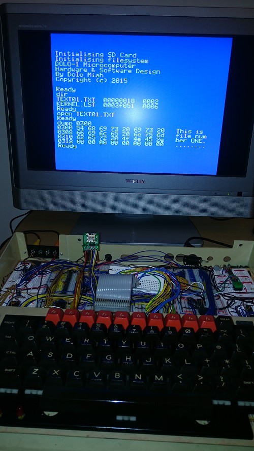
A quick description of what is going on here:
'dir' - obviously displays the directory! But how is quite involved. First, I load up the root directory (which was calculated during initialisation) sector 0. Each 32 byte entry is examined to see if it is a regular 8.3 file. If so, the details of the file are returned for displaying. This carries on until the end of the sector or end of directory. If the sector is exhausted then the next sector has to be loaded and examined. This is because with the 1GB card I formatted using Windows 10, it is reporting that there are 20 sector's work of root directory.
So dir shows two files on the card - TEXT01.TXT, and KERNEL.LST. These are both files I created (in the case of the .TXT) or copied from another directory (in the case of the .LST file). So that tells me that at least the directory structure is being read successfully.
'open' - as you will guess, this opens a file ready for reading. Fundamentally, I reuse the directory scanning routines for dir, but now I am looking for a named file. Once found, I load up various attributes and then load the first sector of the first cluster the file occupies. The approach to do this is fairly involved, but not very complicated once one gets used to it.
'dump' - dumps memory from the location entered. In this case, 0x0300 to 0x4ff happens to be where I have put the raw SD read/write buffer. The dump shows that the open command worked, and is indeed pointing to some content I recognise.
There are a few restrictions which I think I will live with for the moment. One is long filename support. It is quite clever (in my view) how Microsoft added LFN, and not that hard to code up. But for the moment, 8.3 file names are fine. The biggest restriction though is that I will stick with files in the root directory only. This will likely get annoying, but as a means to be able to save and load data, I will stick with it for the moment.
Discussions
Become a Hackaday.io Member
Create an account to leave a comment. Already have an account? Log In.