Close
0%
0%

Ignore this ESP8266 board

I stole from every one. The huzza from Adafruit. Matts breakout board. Al1s board from here. NodeMCUs DevKit.

Similar projects worth following
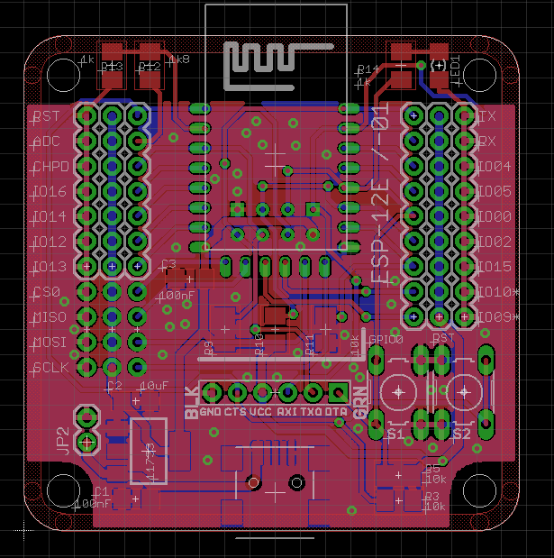
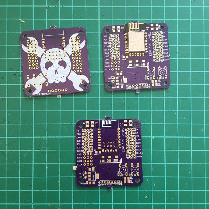
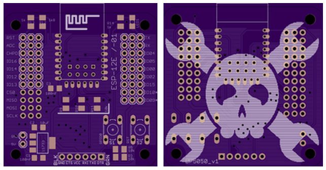
This will be my first http://dirtypcbs.com/ order and since I have ESP-01 and ESP-12 I wanted to have a board that could take them both. I fell in love with GVS rails when I saw them on someones project here. This board follows the usual rules:

Keep GPIO15 LOW (why did they even break it out in the first place?)
Keep GPIO2 HIGH (I've seen it everywhere but some do not specifically say that)

You could also get rid of the reset button, when you just unplug the thing and hit GPIO0 on plugging it back in (HIGH is RUN and LOW is FLASH).

Watch out for the ADC, MAX is 1V (not 1.8V as stated before). That's why I've added a voltage divider.

LED is on GPIO0 now!

There is no extra serial/usb thing on it, cause it would have added extra costs and for experiments it's okay to use a dongle and finished projects wouldn't need programming anyway.

Inspirations/Credits


ToDo

  • check and test CTS and DTR signals - nodeMCU uses transistor magic and adafruit huzza doesn't care, esptool uses auto reset with rts/cts as well as the arduino version - worst case: just not populate the resistors and reset manually

Features


Price

roughly calculated - used parts of packages with various prices (price per part payed multiplied with parts used - you're smart, you'll probably get it just by looking at it) - EUR 5,80 that's around USD 6,50 - with an ESP-12 :)
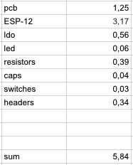
BOM

http://www.esp8266.com/wiki/doku.php?id=esp8266_and_sd_cards


Projects

SickOfBeige_round_case_bottom.stl

Standard Tesselated Geometry - 4.12 MB - 05/07/2016 at 16:44

Download

SickOfBeige_round_case_top.stl

Standard Tesselated Geometry - 1008.51 kB - 05/07/2016 at 16:44

Download

SickOfBeige_round_case_ESP.123dx

123dx - 221.99 kB - 05/07/2016 at 16:44

Download

  • 1 × ESP8266 ESP-01 or ESP-12
  • 6 × 10k Ohm 1206
  • 1 × 1k Ohm 1206
  • 1 × 39k Ohm 1206
  • 1 × 10 uF capacitors

View all 11 components

  • using the ADC with the arduino IDE

    davedarko12/04/2015 at 19:35 0 comments

    I've changed the two ADC resistors to 10k and 3.9k, giving me a range of 0V - 4.9V to be able to check the battery connected to the system.

    Here's a little conversion script for reading and printing the values. I'm high on sugar, so it took me longer than I am able to admit :D

    int r1 = 3883;
    int r2 = 1000;
    
    void setup() {
      
      Serial.begin(9600);
    }
    
    void loop() {
      float val = analogRead(A0);
      
      float vout = (val) * (r1 + r2) / r2 / 1023;
      Serial.print(val);
      Serial.print(" - ");
      Serial.println(vout);
      delay(200);
    }

  • all hand soldered

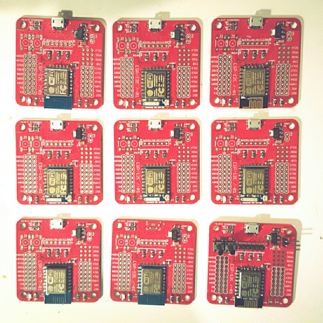
    davedarko11/07/2015 at 20:24 4 comments

  • 15 dirtypbcs!

    davedarko10/07/2015 at 15:02 11 comments

    time for projects... need ideas :D

  • some updates on the 3.3V version

    davedarko08/24/2015 at 14:03 2 comments

    • switched RX and TX signals
    • [fixed thanks @Stefan Lochbrunner] added mini usb footprint (can't find a micro footprint and am a bit too lazy to make one)
    • moved up the FTDI headers and squished the buttons to the side to make room
    • moved 5V input header because it was to near to the screws

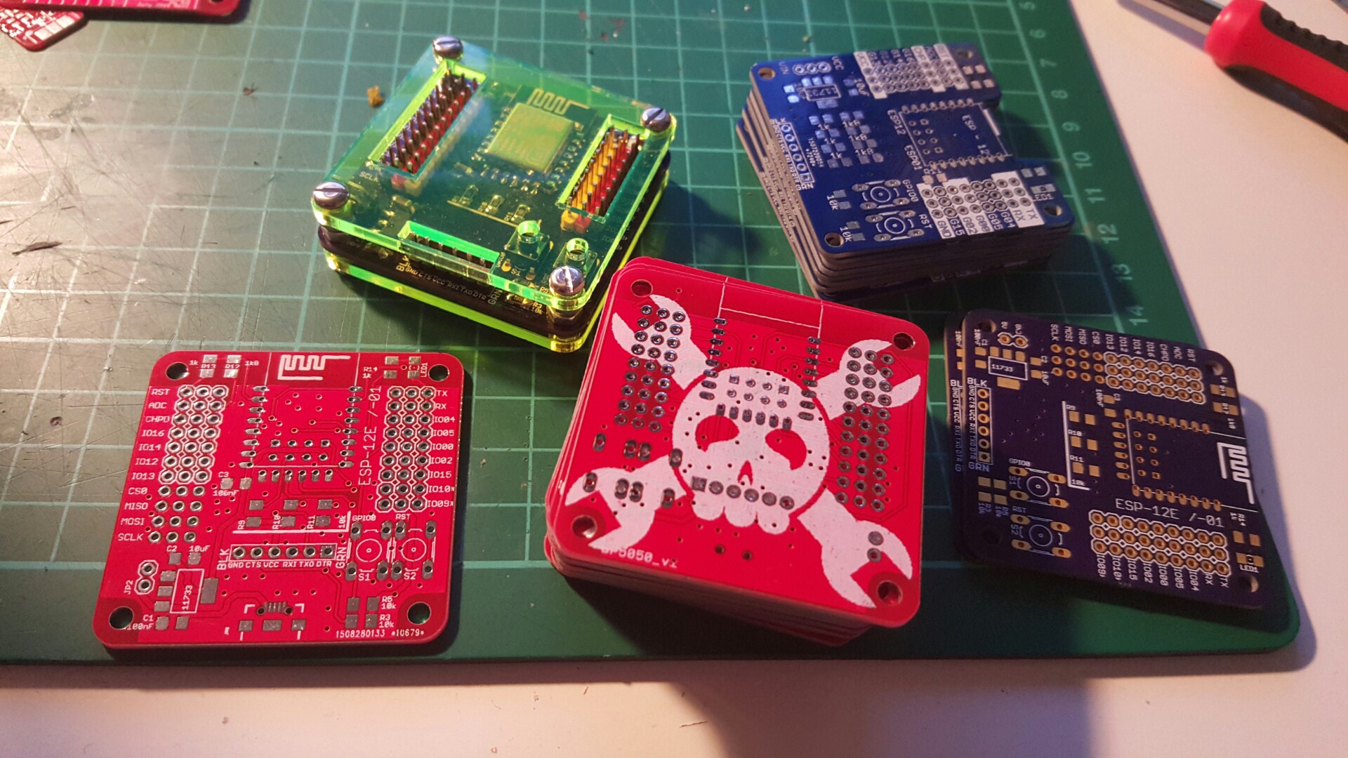
  • dirtyPCBs are in

    davedarko08/17/2015 at 14:14 3 comments

    A bit late, but I like them :)

  • some notes

    davedarko08/04/2015 at 20:38 9 comments

    • I should compare the pinouts of my FTDI dongles, they seem to be different on RX vs. TX
    • the pin holes for the ESP-01 version are way to tight
    • I might add another 10uF cap near to the ESP module
    • USB micro footprint for 5V in ?

  • boards are in

    davedarko08/04/2015 at 09:02 2 comments

    I'm a bit soldering shy right now, because tomorrow I'll fly to Marrakesh because of work. Don't be jealous, it's hot over there 40C - 104F and I won't be on a vacation!

    Anyway, I'm so behind with the ESP8266 that I really look forward to do something with it. As soon as I have validated this board, I'll update the github repo and make a fixed link to OSHPark and dirtypcbs, maybe a log where people can exchange boards if they have plenty - that would be cool.

  • a general dissatisfaction with the overall situation and why dirtypcbs.com is awesome

    davedarko07/20/2015 at 11:33 5 comments

    "a general dissatisfaction with the overall situation" - that's a loosely translation of a german movie quote which describes my feelings with the postal offices in Germany. So it might have been, that the boards where already as close as 20m (that's 60feet?) from my flat, but I wasn't around to pick it up since I was in America at that time and my flower watering guy was not able to pick it up from the post-office where it was brought to because I did not write an warrant. I still wonder why a 16mm package wouldn't fit in my post box, but anyway. My flower guy told me that only yesterday, so with 2 weeks of holding time for international packages they probably got send back.

    So I wrote exactly that to the dirtypcbs.com guys and they replied pretty fast ( < 1 hour), considering their disclaimer, and they will make new ones and send them to me! Awesome! Makes me want to create 10x10 boards now.

  • 12E board ordered

    davedarko07/18/2015 at 22:04 0 comments

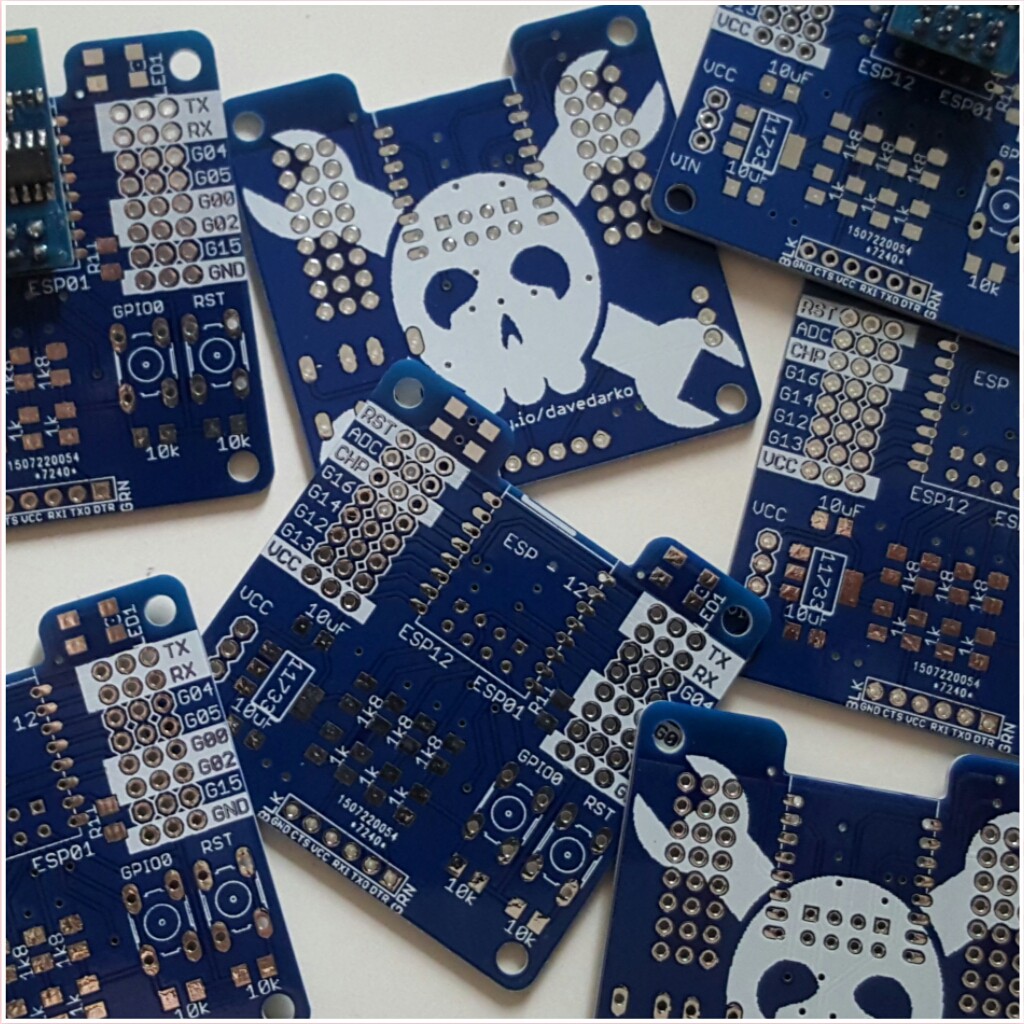
    So since my boards I ordered at dirtypcbs.com are still not here I took the time and designed the 3.3V 12E version and ordered it at OSHpark - almost 20bugs for 3 boards, but I want them badly, so I ordered them! They are also Sick-Of-Beige compliant.

  • waiting...

    davedarko07/16/2015 at 21:28 0 comments

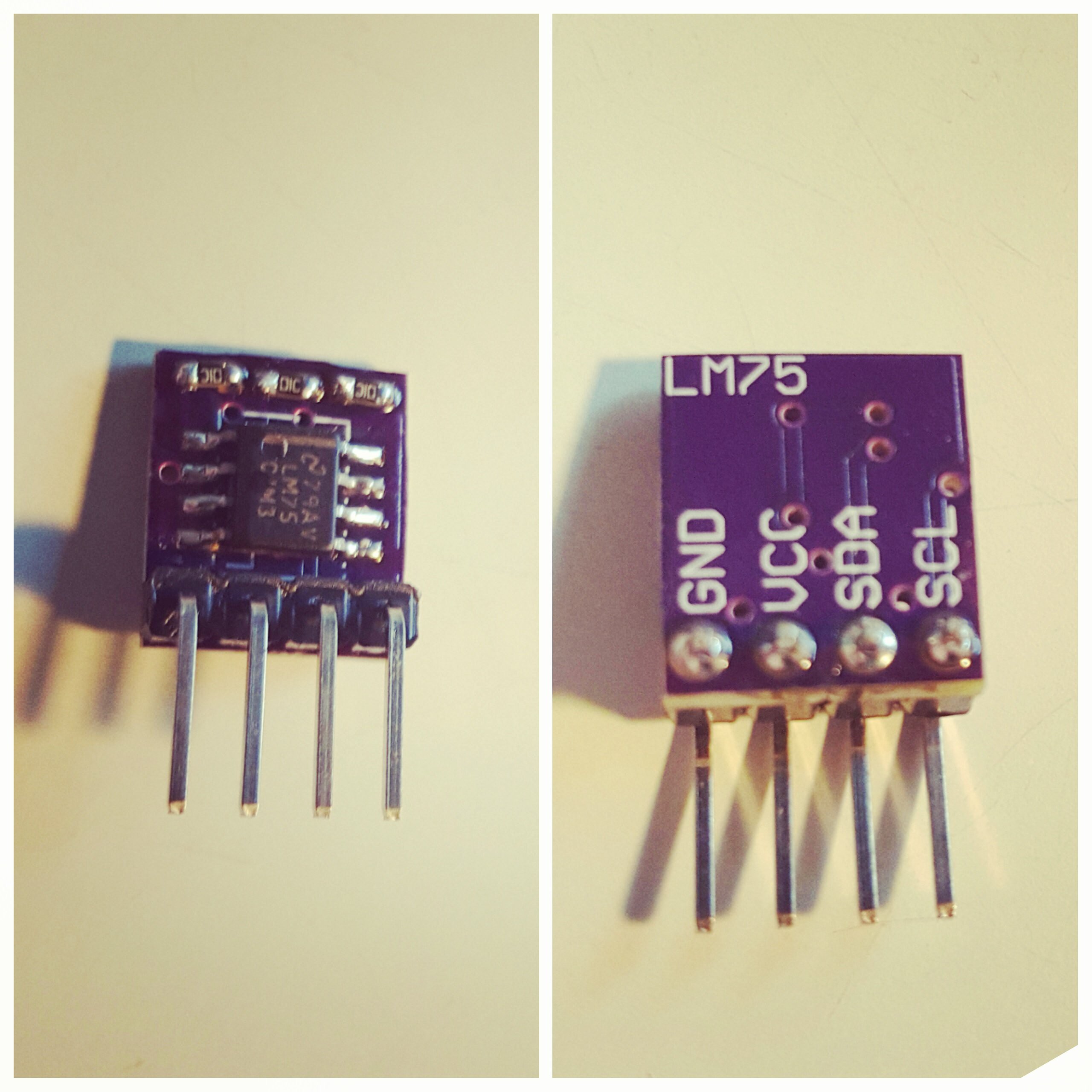
    Hmm, 5 weeks away and the boards are not here yet :( I got the LM75 boards though.

    // wire is no hardware I2C but software 
    #include <Wire.h>
    int t,l;
    void setup() {
      Wire.begin(); // pins 2 and 14 are SDA and SCL by default
      Serial.begin(9600);
      Serial.println("Reading the LM75");
    }
    
    void loop() {
      Wire.write(0x00);
      // 0x48 or 0xC8
     //  B1001111
      Wire.requestFrom(0x48, 2);
      while(Wire.available()) {
        int8_t msb = Wire.read();
        int8_t lsb = Wire.read();
        // strip one bit of the lsb
        lsb = (lsb & 0x80 ) >> 7; // now lsb = 0 or 1
        // add to to form an float
        float f = msb + 0.5 * lsb;
        Serial.println(f,1);
      }
      delay(1000);
    }

View all 17 project logs

Enjoy this project?

Share

Discussions

Morning.Star wrote 06/12/2018 at 18:45 point

Kudos for having no shame lol, thats funny dude. :-)

  Are you sure? yes | no

davedarko wrote 06/12/2018 at 23:18 point

well it wasn't anything I sold anyways... :)

  Are you sure? yes | no

Jarrett wrote 06/12/2018 at 23:33 point

But I bought one of these on AliExpress! That wasn't you?!

  Are you sure? yes | no

davedarko wrote 06/13/2018 at 07:11 point

@Jarrett  that would be pretty awesome if true!

  Are you sure? yes | no

Jarrett wrote 06/13/2018 at 07:12 point

It's not :(

  Are you sure? yes | no

Josh Starnes wrote 06/10/2018 at 19:12 point

The first thing I thought of was how much this reminds me of the V4 version of Ez-Robots board.  Any good at Pi code? python 

  Are you sure? yes | no

davedarko wrote 06/10/2018 at 19:17 point

Probably the only board I didn't steal from ;) I've made a list of projects where I took inspiration from. I'm really bad at coding in python, anything I did on the PI was with wiring.

  Are you sure? yes | no

limweiyap wrote 08/18/2016 at 05:55 point

Good work! Do you sell these boards?

  Are you sure? yes | no

Alex wrote 08/12/2015 at 18:59 point

Nice case. I really like the idea of the colored pinheaders. Are the black and red 3,3V and GND? You could use push buttons with a longer shaft (like these: http://www.reichelt.de/Kurzhubtaster/TASTER-9305/3/index.html?ACTION=3&GROUPID=3278&ARTICLE=44586&OFFSET=16&WKID=0& ). So the buttons are reachable without a screwdriver. 

  Are you sure? yes | no

davedarko wrote 08/12/2015 at 19:07 point

Thanks :) using sick-of-beige from the dirtypcb/dangerousprototype gang was a good idea you had! I wanted the yellow/green thing because of the blue LED on the GPIO. Yes, red is VCC, black is GND and yellow is signal (colored GVS headers are awesome) - I've already ordered buttons with longer shafts. I have to move the power supply pins or swap them with usb micro. 

  Are you sure? yes | no

Scottjfaulkner wrote 07/03/2015 at 06:22 point

Could you please provide a link to your board (with the 12e) on dirtypcbs to make it easy for us to order? Cheers, SJF

  Are you sure? yes | no

davedarko wrote 07/03/2015 at 16:04 point

I wanted to test the esp12 boards first.. here is the link to the them, NOT the ESP12E  http://dirtypcbs.com/view.php?share=7240&accesskey=c91fff8304e1db6f70933aeb5d9a8747

  Are you sure? yes | no

David Ogilvy wrote 06/27/2015 at 04:45 point

GPIO2 needs to be pulled high, and GPIO15 pulled low for both SPI Flash boot and Serial Bootloader modes. GPIO0 is then high for SPI Flash Boot and low for Serial Bootloader. 

People are getting away with not pulling GPIO 0&2 high because the pins have internal weak pullups that are enabled by default. 

There's some more info on the bootselect strapping in some of the Espressif documentation. GPIO2 pulled low enables some of the SDIO modes which are not usable with these modules the way they are connected (SDIO lines are already connected to the on-module flash chip).

  Are you sure? yes | no

Neon22 wrote 06/20/2015 at 05:17 point

for the ADC voltage - if you added one pair of pads - in parallel with the voltage divider resistor - and indicated what the value would be for a 3.3V divider - that would be useful IMHO.

  Are you sure? yes | no

davedarko wrote 06/20/2015 at 13:29 point

Hey, thanks for your input! There are labels for a 1.8k and a 1k resistor on it on the latest revision, but that was based on the assumption that a 5V max signal was given to an 1.8v adc. Since I've learned it's more likely a 1v adc you should be fine with a 2.2k - 1k setup for 3.3V. I probably want to check the power supply, so a bigger ratio was what I needed.

  Are you sure? yes | no

cmduarte wrote 06/08/2015 at 15:42 point

Nice. I, too am a "cookbook" engineer......a little of this circuit, a little of that, mix together to get what I want. I probably have a library of 2000 different circuit diagrams dating back to the '70's. I just wish I had more time.  Wait a minute! Did I see a time machine circuit somewhere?

  Are you sure? yes | no

davedarko wrote 06/08/2015 at 21:09 point

I want to be a time lord :) having a time machine would be great, but not having the time to use it, would be unacceptable. If there's a circuit for it, please prolong my life and anyone else's ten times or more.

  Are you sure? yes | no

bench2004 wrote 06/05/2015 at 07:31 point

So got the new board yet? and does it work?

  Are you sure? yes | no

davedarko wrote 06/05/2015 at 07:46 point

I'm still waiting for the first boards to arrive... thanks for the interest and skull :) I hope the boards will be here before I'm gone for 4 weeks.

  Are you sure? yes | no

frankstripod wrote 05/17/2015 at 06:52 point

How could I ignore anything you do at HaD? :)

  Are you sure? yes | no

davedarko wrote 05/17/2015 at 07:48 point

hehe :) thanks for the skull and following! I wrote this because there are so many boards here and I stole mine together :) and people don't like to be told what to do, so yeah - it's also a trick to get attention :D 

  Are you sure? yes | no

Does this project spark your interest?

Become a member to follow this project and never miss any updates