 davedarko
Inspirations/Credits
- https://hackaday.io/project/5231-esp8266-esp-0712-dev-board - form factor inspiration and decision making helper for ordering at dirtcheap PCBs ( @al1 )
- https://hackaday.io/project/5728-esp8266-01-breakout Matt's ( @technolomaniac ) tutorial I attended which gave me an incredibly good starting point
- https://learn.adafruit.com/adafruit-huzzah-esp8266-breakout/overview Adafruits huzzah
- https://github.com/nodemcu/nodemcu-devkit NodeMCU devkit
ToDo
- check and test CTS and DTR signals - nodeMCU uses transistor magic and adafruit huzza doesn't care, esptool uses auto reset with rts/cts as well as the arduino version - worst case: just not populate the resistors and reset manually
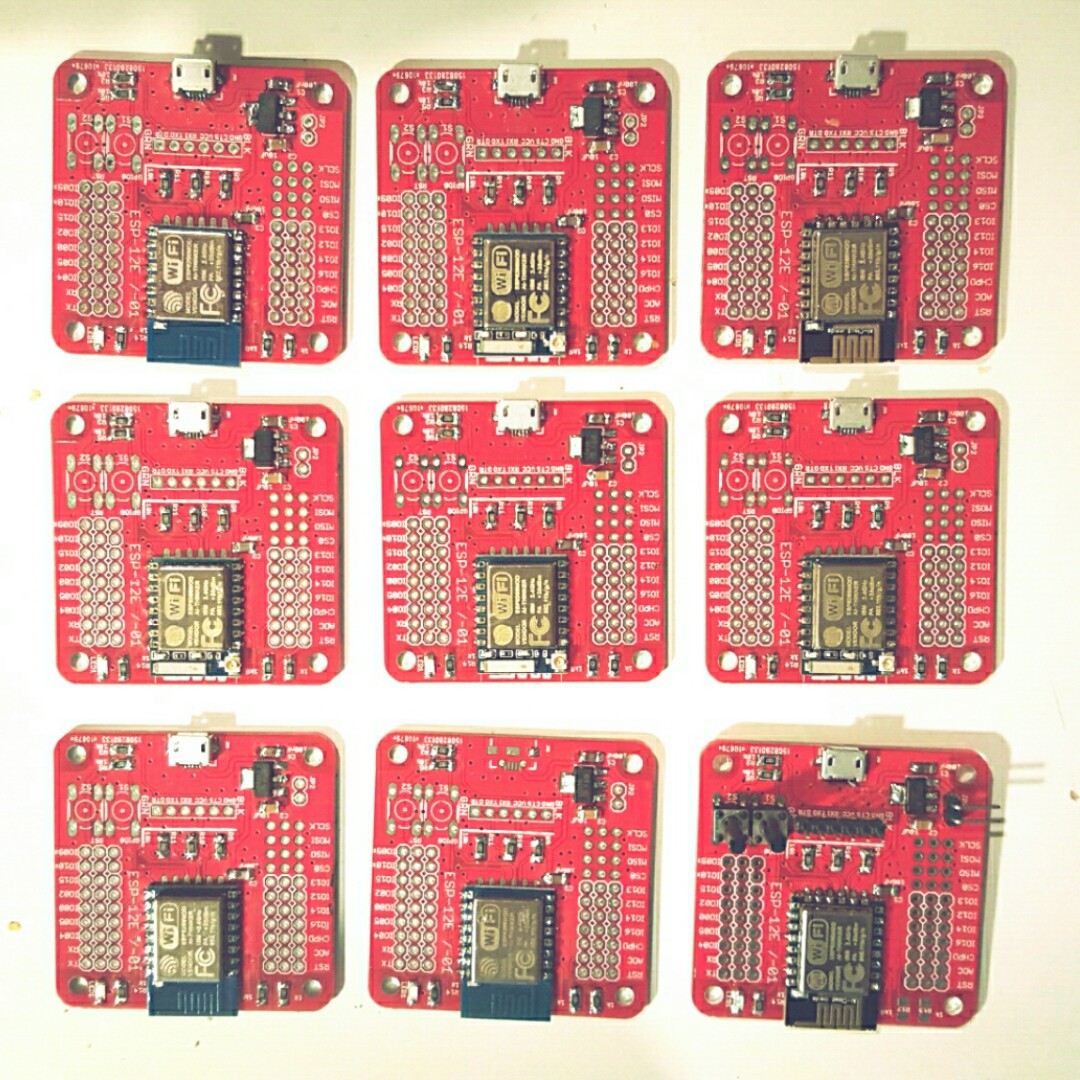
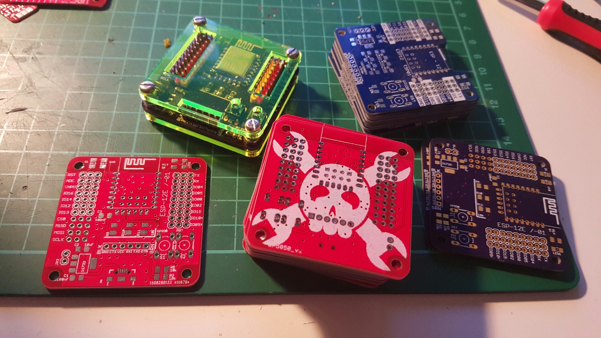
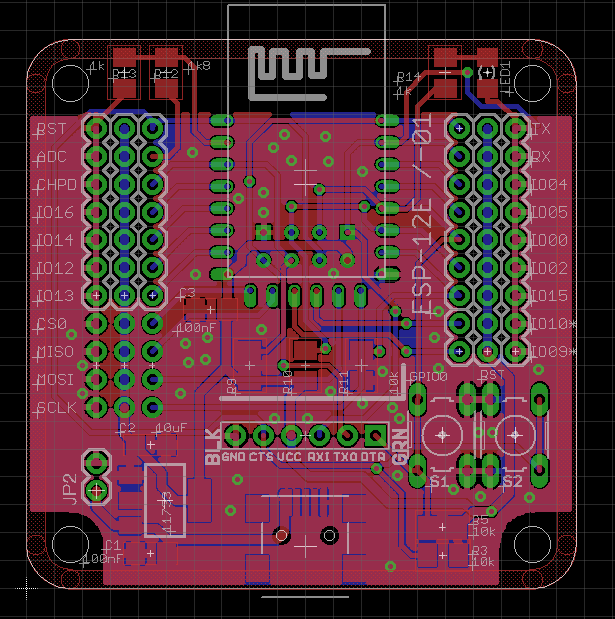
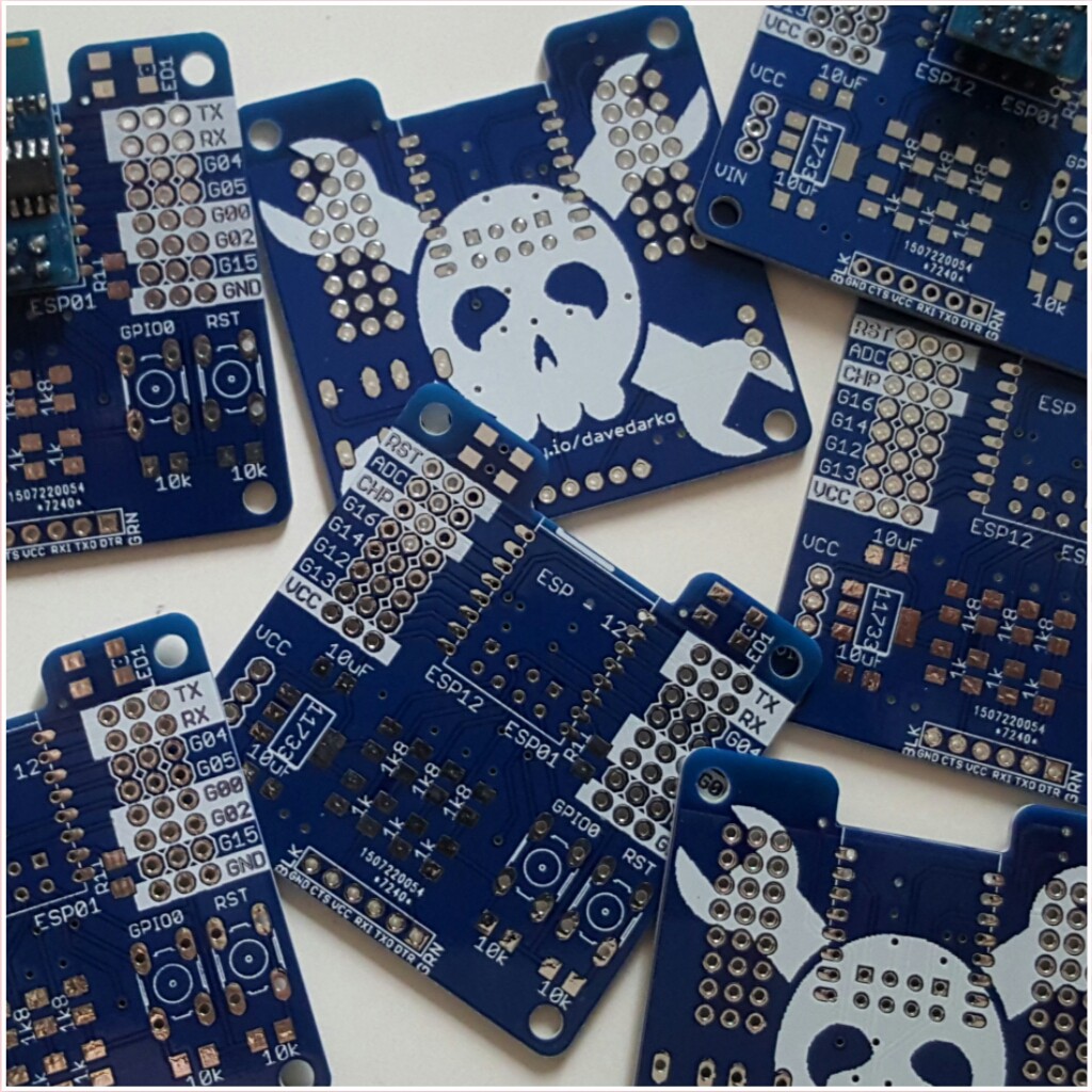
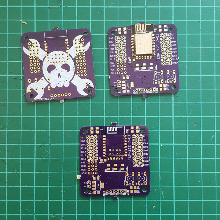
Features
- 4.5V ADC (with 10k and 39k divider - feel free to change!)
- 3.3V regulator on board (http://www.st.com/web/en/resource/technical/document/datasheet/CD00002116.pdf)
- LED on GPIO0
- FTDI serial port (5V only)
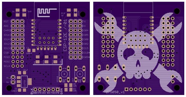
- breakout for ESP-01 and ESP-12
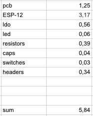
Price
roughly calculated - used parts of packages with various prices (price per part payed multiplied with parts used - you're smart, you'll probably get it just by looking at it) - EUR 5,80 that's around USD 6,50 - with an ESP-12 :)
http://www.esp8266.com/wiki/doku.php?id=esp8266_and_sd_cards
Projects
- #ESP8266 RFid reader
- #I'm a fan of your fan
- #fixietube clock - the smaller brother with only two jam jar sockets


 T. B. Trzepacz
 Gabriel
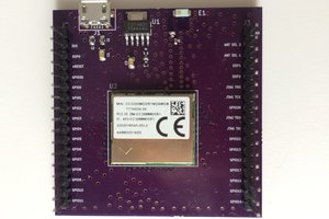
 Jackson Keating
 Luke Valenty
Kudos for having no shame lol, thats funny dude. :-)