 C. Prichard
Living Off-Grid in Wales UK - (inverter overloading confirmed)
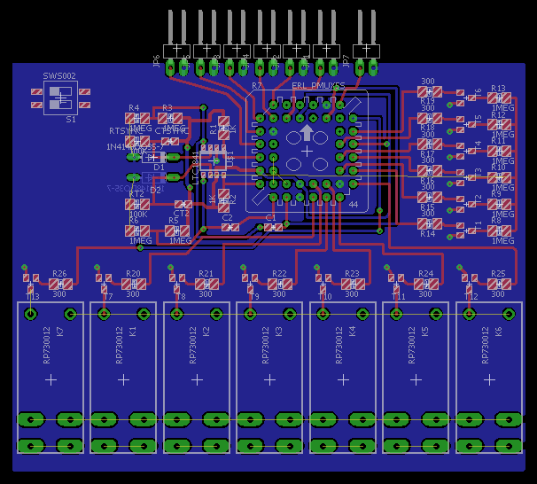
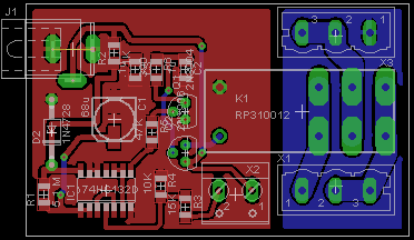
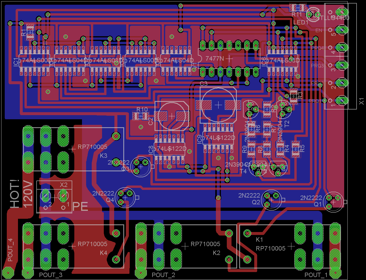
LAST UPDATE: 3-21-16 ATF1500A logic infusion. Resistor arrays? Open area is for DC supply components. Compare to the picture at the bottom.
Achieved WINCUPL compilations of three PAL devices. ATF1500T allows consolidation desired for concise design, reprogrammable, configurable, easily manufactured. Am now working to consolidate this effort to include the WINCUPL output for the ATF1500T, and other components, associated EAGLE components, and LTSpice simulations.
WINCUPL ATF1500T logic (below)
Improved logic integration resulted from attempt to design the board for testing the time base. I realized the logic gates can be added to the programmable logic array device. I need to port this part of the project out, but it makes the build much better for manufacture.
Result is a simpler-looking design. I decided the time base is not easily implemented using OTS parts. When seen this way (below) it looks pretty good.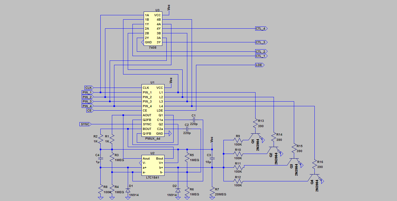 I'm looking for someone to program the logic.
BTW: A nice feature of the Inductive Load Center device is that it becomes practical to then disable the controlled devices, favoring use of power tools without interruption from a pump or other load. Just a flip of a switch can eliminate inconvenience, and resetting the inverter.
1-22-16 Progress at an implemtation of the retriggerable, free-running 2-phase monostable. (I could not get a 555 simulation to retrigger. I had to try.) Thus, I simplified my implementation, consolidating, using two LT1841 comparators. There can be modes: free-running retriggerable (VLFO), gated retriggering, synchronized mode, and single shot mode. I created a simulation using a short 10ms sync pulse with ten second duty pulse. For the model to work as intended, the incoming sync pulse must be debounced, and less than 10ms. This is not a bad building block, a variation of the 555, easy to use, and probably capable of doing a few things for which the 555 is not well suited.
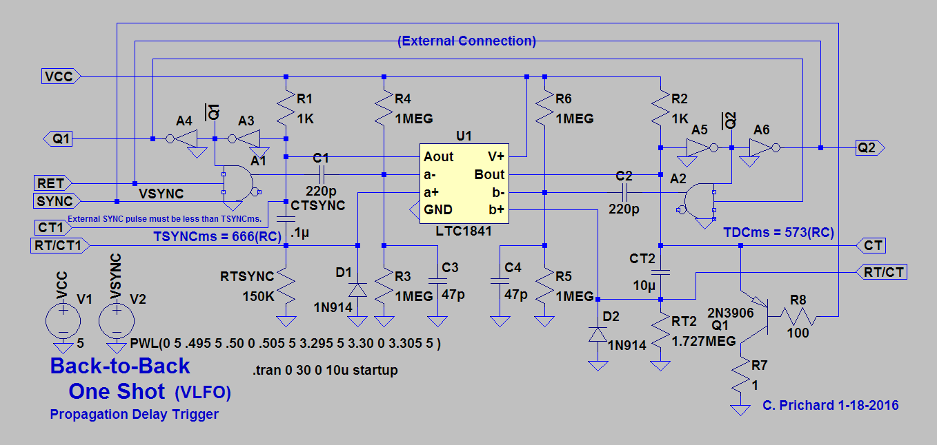
BTB1S Drawing is of an implementable version. Propagation delay puts a trigger on inverting input, driving comparator to runaway. Output charges timing capacito. Not sure how it discharges... this can actually be implemented.
ILC PROTO SOURCE CODE I added a software implementation of the DUMMY CARD feature. This code compiles, and will allow me to create a tool for tinkering with user interface with simple LED's and buttons. It will be possible to implement a program mode to adjust delays. Am thinking to try thumb-wheel resistor setup... I will add some comments, and document the DUMMY implementation.
Am looking at software implementation of the DUMMY CARD for Arduino.
Briefly, it presents a user interface problem. Looks like a solution begs for an adjustable analog input value for each activated DUMMIED sensor. Is easy to call DCPRQ_update to update PRQ status if the delay is expired. This call would be in an if-else that determines if the DC option is in use. The function will require external values, and simply use them to return a result for each installed DC option. This is to determine downtime delay between PRQ requests. Example, it could be twenty minutes for the sensorless septic pump. The delay value could be adjusted with a voltage on one of the analog inputs.
In the function below, DC_ltime is read when a new DC_PRQ delay is begun. The time value is stored with the desired delay_PRQ value and are passed into the function to be used and compared with present time. Result is HIGH or LOW, and used to update the associated PRQ_State value.
int DCPRQ_update(unsigned long DC_ltime, long delay_PRQ ) {

	unsigned long ptime = 0;
	long Timer = 0;

	ptime = millis();
	Timer = ptime - DC_ltime;

	if (Timer >= delay_PRQ){return HIGH;}

	return LOW;

}
Another possibility is to provide the hardware DC option based on a 555 timer implementation. I worried that it might be difficult to implement the retriggerable 1SHOT, but a 555 can be used, retriggerable after the delay is expired. The hardware DC option might be preferable as it would allow RC time constant adjustment. The hardware DC applies a PRQ signal same as will a sensor. Only difference is that the DC will not change state until timeslice expiration.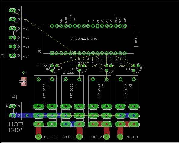
Debugged Arduino Micro code:
Added a few lines to accept and echo serial USB input.
/*
INDUCTIVE LOAD CENTER ILC(prototype)
Charles Prichard
12 December 2015
ILC: An important device to prevent inverter overloading caused by multiple inductive loads.
LTSPICE simulation using discrete component models was created featuring a back-to-back retriggerable
monostable concoction. Lack of interest in the invention gives cause to creating the programmable
prototype version. This will actually lead to an easier-to-implement piece of hardware, and bypass
a development phase to accommodate anyone wanting to program new applications for this circuit which
can possibly be ported to the retriggerable monostable version.
Program logic for prioritization is less than expected. Note there is memory for more program features.
Arduino Micro provides a small 34-pin footprint to drop into a board with driver transistors, relays,
and sensor conditioning, or my dummy sense implementation.
I heard via NPR story a few days ago of renewable system in Wales UK, where use of too many devices would
overload the inverter. This story was interesting as the location is the site where Led Zeppelin was inspired
to write "Stairway to Heaven," and an expensive wind turbine is used. Lack of a device to limit inductive loads
to prevent overloading, provides greater assurance there is no device like the ILC in the world.
I recently replaced two cables from 24-volt battery bus to inverter to improve performance. Now, voltage drop is
only 1-volt into the inverter when pumping water, or the septic. The pumps take less time, operating more
efficiently. I burned my finger on one of the battery type connectors to #4 aluminum wire. Wire is now #2 copper,
and connectors are crimped. The water pumps noticeably faster to repressurize, and the septic requires about ten seconds.
Before changing cables, low voltage was indicated most of the time. Now, it does not happen unless battery voltage is
less than 23 volts. The aluminum cables and connectors were deteriating.
Target: Arduino Micro
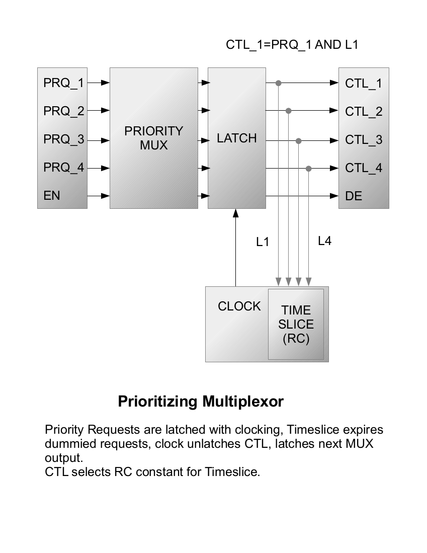
This code intends to read four priority request (PRQ) inputs labeled 6,7,9,10 on the Arduino board.
Based on input a single prioritized output on pins 2,3,4,5 is articulated with prioritization by order of processing.
A predefined timeslice is used to allocate inverter power by driving four relays to switch line voltage
via the prioritized output and a driver transistor.
In cases where a sensor is driving the PRQ input signal, as the sensor is polled affecting prq_State, power will be unswitched.
Testing prq_State allows a control loop test to fail, resulting in switching off the driven relay ahead of a timeout
which will otherwise do so.
I decided to read composite PRQ inputs during the sync loop, reducing response time to sensor input in the timeslice loop.
A sync pulse and 1sec delay is generated between timeslice loops.
Switch on the board is reset. Use of pin8 as switch pin input is programmed to expire an active timeslice.
It may be possible to sense battery voltage and sunlight, asserting power for automated air purification and other use.
This would be the beginning of creating additional features via programming.
*/
// Global Constants
const char* global_hello = "ARDUINO MICRO";
const int swPin = 10; // switch pin reference
const int led = 13; // LED reference
const int prq0_Pin = 2; // references for PRQ0-PRQ3 input pins
const int prq1_Pin = 3;
const int prq2_Pin = 4;
const int prq3_Pin = 5;
const int p0_Pout = 6; // references for P0-P3 output pins
const int p1_Pout = 7;
const int p2_Pout = 8;
const int p3_Pout = 9;
const int sync_Pout = 11; // sync output pin reference
// 600000 = 1 minute in milliseconds
const long delay_Sync = 100; // 100 millisecond sync pulse
const long tsl_P0 = 10000; // P0 timeslice (10 seconds, adjust for desired delay.)
const long tsl_P1 = 100; // P1 timeslice
const long tsl_P2 = 600; // P2 timeslice
const long tsl_P3 = 600; // P3 timeslice
// Global Variables
int charVal;
String instr = "";
char ch;
int prq0_State = LOW; // loop PRQ_0 state
int prq1_State = LOW; // loop PRQ_1 state
int prq2_State = LOW; // loop PRQ_2 state
int prq3_State = LOW; // loop PRQ_3 state
unsigned long pTime = 0; // present time
unsigned long lTime = 0; // beginning loop time
long Timer = 0; // loop timer
// int swState = 0; // current switch state
long timeslice = 0;
void setup() {
Serial.begin(9600);
splash();
pinMode(led, OUTPUT); // set the LED pin as output
pinMode(sync_Pout, OUTPUT); // set the syncOut pin as output
pinMode(p0_Pout, OUTPUT); // set the prioritized output pins as outputs
pinMode(p1_Pout, OUTPUT);
pinMode(p2_Pout, OUTPUT);
pinMode(p3_Pout, OUTPUT);
// pinMode(swPin, INPUT); // set the switch pin as input
pinMode(prq0_Pin, INPUT); // set the priority request pins as input
pinMode(prq1_Pin, INPUT);
pinMode(prq2_Pin, INPUT);
pinMode(prq3_Pin, INPUT);
digitalWrite(led, LOW); // Initialize LED LOW
}
void splash(){
while (!Serial.available()){}
digitalWrite(sync_Pout, HIGH); // generate a sync pulse
Timer = 0;
lTime = millis();
do { // This delay can be interrupted.
pTime = millis(); // Is also useful for input sense
Timer = pTime - lTime;
}
while (Timer < 1000);
digitalWrite(sync_Pout, LOW);
Serial.println(global_hello);
}
void loop() {
// declare and assign loop variables
int prqState = LOW; // Used to determine if demand is fulfilled.
int pOut = LOW; // Used to set and clear output assertion.
int prq_Pin = LOW; // Used to remember which input to test for state change.
int ptr = LOW;
char* buf[32];
digitalWrite(sync_Pout, HIGH); // generate a sync pulse
Timer = 0;
lTime = millis();
do { // This delay can be interrupted.
// Read the PRQ inputs
// prq0_State = HIGH; // prq0_State = digitalRead(prq0_Pin);
prq0_State = digitalRead(prq0_Pin); // TEST here verifies PRQ inputs are HIGH unless pulled LOW.
prq1_State = LOW; // prq1_State = digitalRead(prq1_Pin);
prq2_State = LOW; // prq2_State = digitalRead(prq2_Pin);
prq3_State = LOW; // prq3_State = digitalRead(prq3_Pin);
pTime = millis(); // Is also useful for input sense
Timer = pTime - lTime;
}
while (Timer < delay_Sync);
digitalWrite(sync_Pout, LOW);
if (prq0_State = HIGH) { //Can program a switch to reverse priority...
prq_Pin = prq0_Pin;
timeslice = tsl_P0;
pOut = p0_Pout;
}
else {
if (prq1_State = HIGH) {
prq_Pin = prq1_Pin;
timeslice = tsl_P1;
pOut = p1_Pout;
}
else {
if (prq2_State = HIGH) {
prq_Pin = prq2_Pin;
timeslice = tsl_P2;
pOut = p2_Pout;
}
else {
if (prq3_State = HIGH) {
prq_Pin = prq3_Pin;
timeslice = tsl_P3;
pOut = p3_Pout;
}
}
}
}
if ((prq0_State = LOW) && (prq1_State = LOW) && (prq2_State = LOW) && (prq3_State = LOW)){
timeslice = 100; // default timeslice if no PRQ inputs HIGH
pOut = led;
}
digitalWrite (pOut, HIGH); // Generate a timeslice
digitalWrite (led, HIGH);
Timer = 0;
lTime = millis();
do {
if (Serial.available()){ charVal = Serial.read();}
if (charVal){
digitalWrite(led, HIGH); // set LED on
// delay(1); // wait
ptr++;
instr.concat(char(charVal));
Serial.write(charVal);
Serial.write(32); // space to obviate TX emanation
charVal = 0;
digitalWrite(led, LOW); // set LED off
// delay(1); // wait
}
if (pOut != led){prqState = digitalRead(prq_Pin);} // Test prq_Pin for state change
// prqState = HIGH;
if ((pOut != led) && (prqState = LOW)){break;} // Sensed input ends pOut assertion
pTime = millis();
Timer = pTime - lTime;
}
while (Timer < timeslice);
digitalWrite(pOut, LOW); //Timeout ends pOut assertion.
digitalWrite(led, LOW);
charVal = 0;
ptr++;
instr.concat(char(charVal));
Serial.println(instr);
instr = "";
} //LOOP
7-27 I will say it would be interesting to see how the application code looks in the upper-level Arduino programming language. Prototyped with Arduino, it would then be easier to develop and prototype new applications for the same device.
It has occurred to me to seek a programming service to put the PMUX into a PAL. Not sure, but I think there are gates in the Atmel ATF22LV10C or similar, to achieve simplicity. It may be possible to include the latch as well as logic for six lines. With the PAL, a small 8-bit processor can be easily programmed, and do the latching. The main board would include only PMUX PAL, processor, driver transistors, and relays. Simple. I see little benefit of prototyping with Arduino, except to show simplicity, as it is simulated and easily producible without processor. The processor design would emulate the back-to-back monostable with delays. It would be the most difficult part of the programming, using one or two of the timers, and an interrupt.
Long-term development may prefer the processor, thinking to be ready to employ advanced computation to determine timeslice values on the fly, in response to environmental or other input, in new applications for the same circuit. It can be used to dynamically control fans, pumps, motors in response to conditions as well as the PRQ signal.
7-25 Added modified simulation to increase clock frequency when PMUX input is void.
7-14 Edited DUMMY CARD BLOCK DIAGRAM, created LTSPICE DUMMYCARD model and simulation.
DUMMY CARD is simple.

The LTSPICE model.

Design/conceptualization phase:
NEC is strict, requires intended use of components. As DPST Pump pressure switch transfers AC, it would be an argument that one might transfer AC through a step-down transformer, detecting presence of secondary voltage as logic. In one context it is arguable that the switch is used as intended to transfer AC power. I think the industry would lose if they decided to fight.
Thus, my problem becomes that of finding ways to give inductive load devices timeslices to derive the conveniences they deliver.
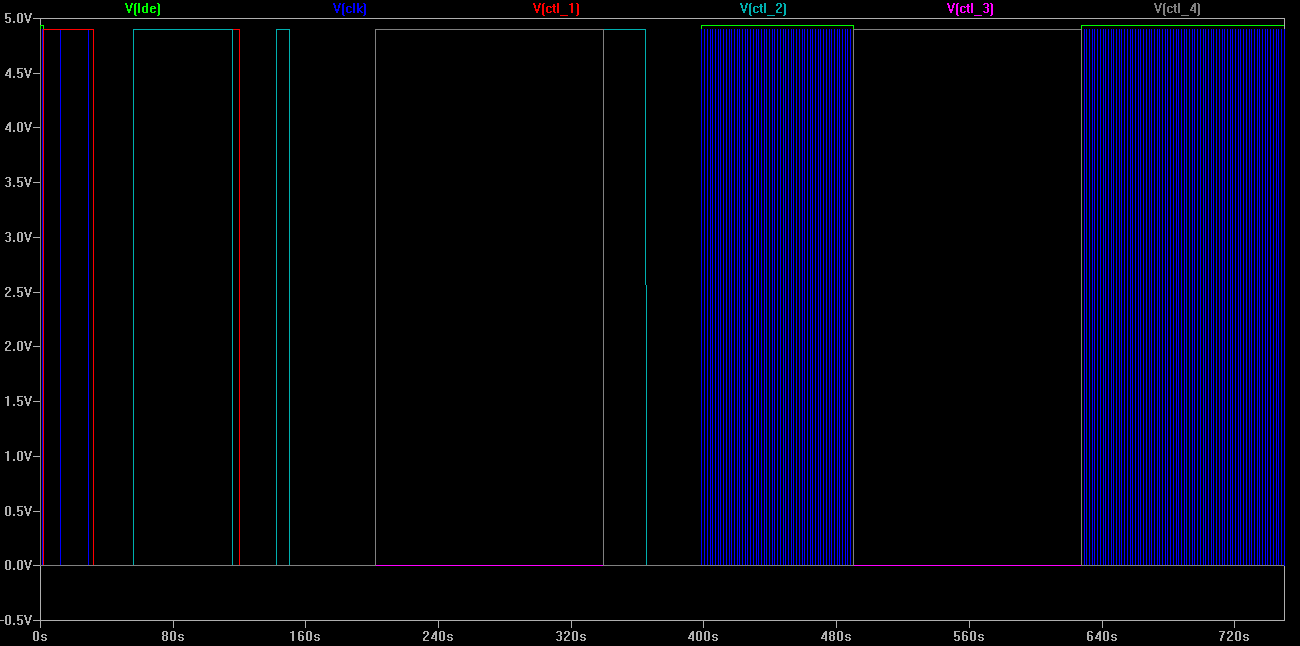
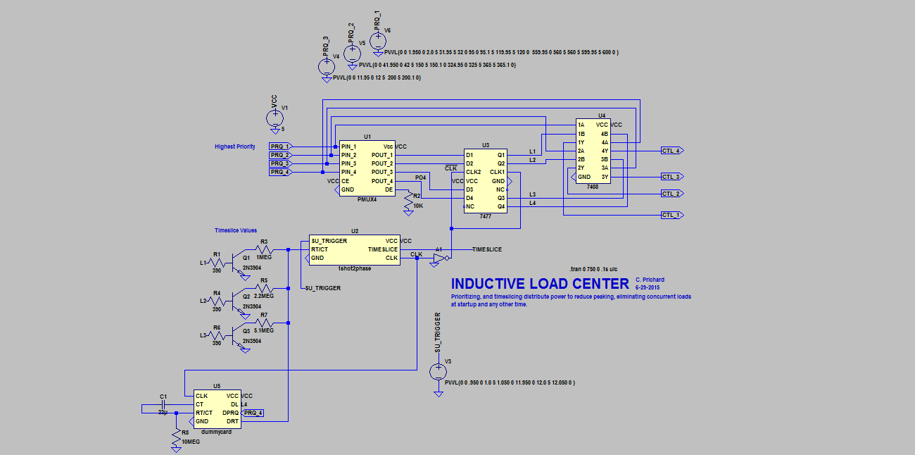
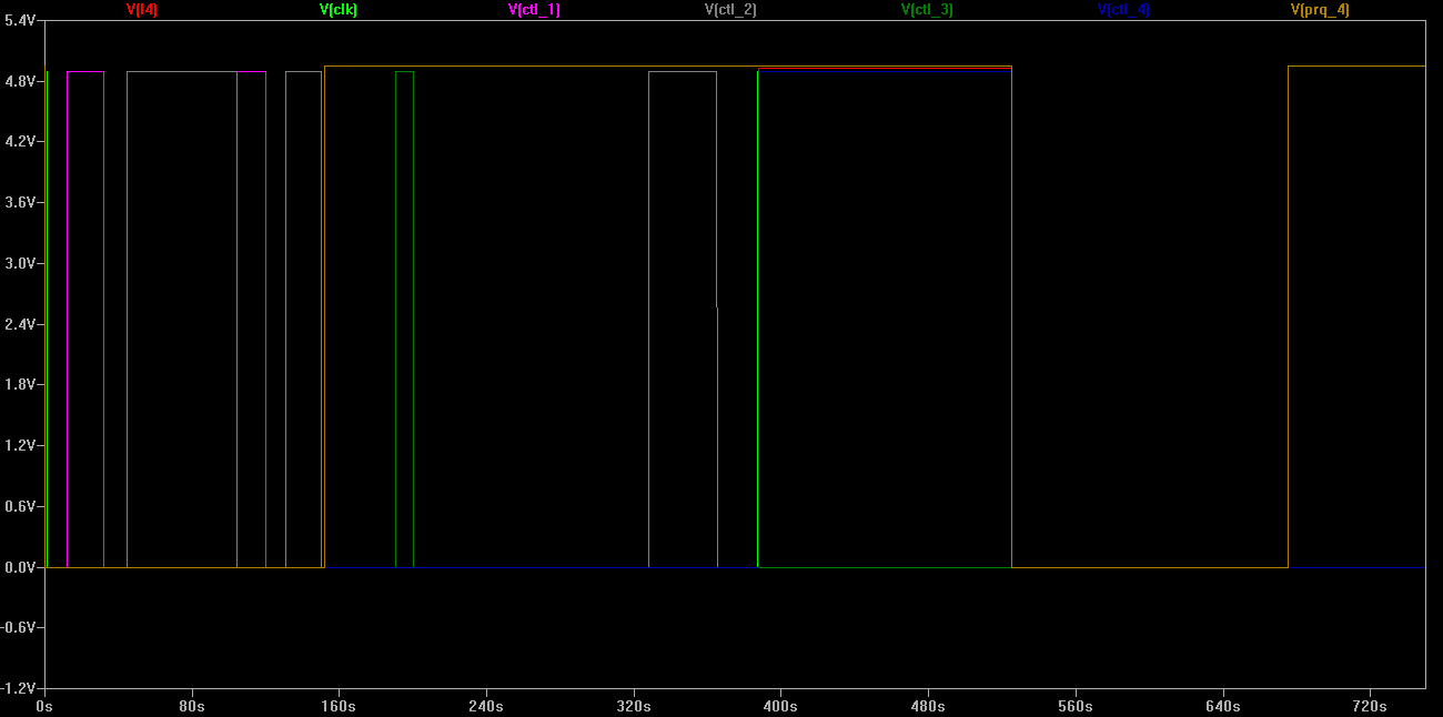
 Above: With variable timeslices loads1,3,4 are selected. Load 4 exceeds its timeslice, and at expiration clock latches load 1 (which also exceeds its timeslice.) At next clock, load 4 is again selected, and it completes early, ahead of timeslice expiration.
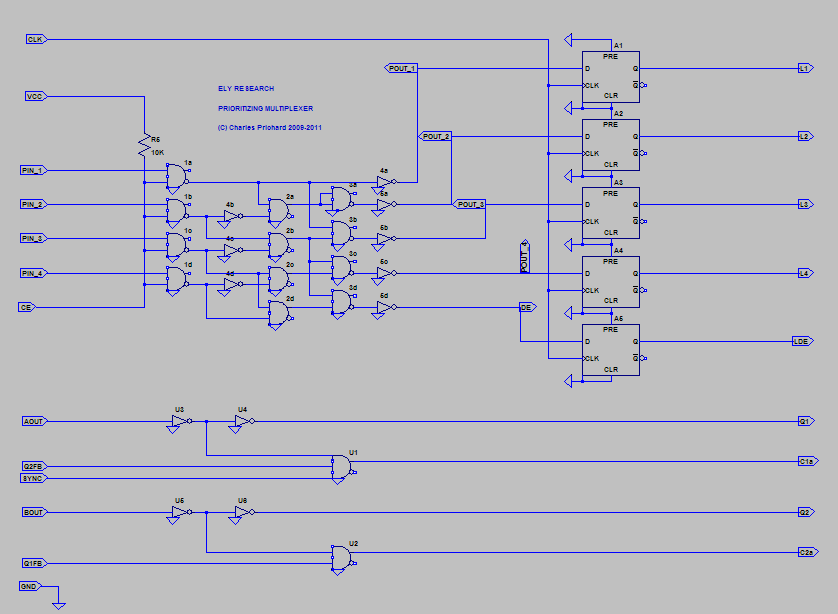
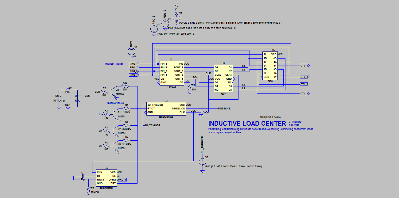
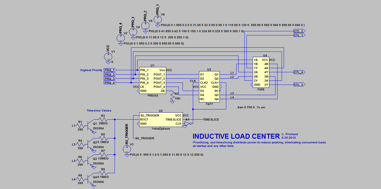
I conceived of, implemented, and simulated the Inductive Load Center logic and clocking in LTSPICE!

This is a novel solution to the problem of handling concurrent switching of inductive loads at inverter startup, and continuously. It does not use a micro-processor. Check it out!

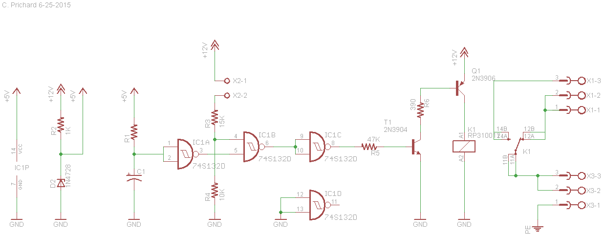
Actual schematic
UPDATE 6-29-2015 C. Prichard (see bottom)
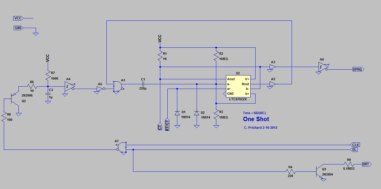
Sensing from the pressure switch can be adapted to 5-volt logic, and N.O. N.C. relay conditions define pump control states. I diagrammed a 555 timer in one-shot configuration to limit duration for pumping the well. Normally this is okay, but if watering the garden, it may be inconvenient. As shown, the septic pump will be enabled any time the pressure switch AND the 555 output are not coincidentally HIGH. A manual override for this feature may be necessary.
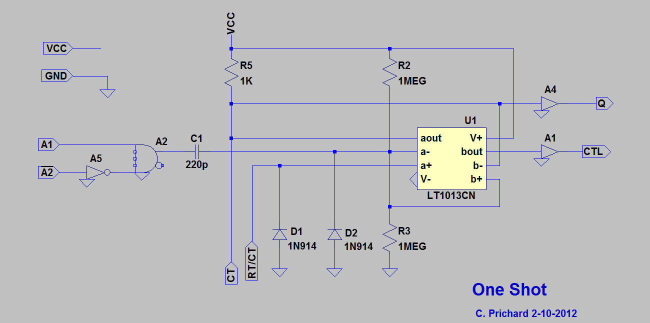
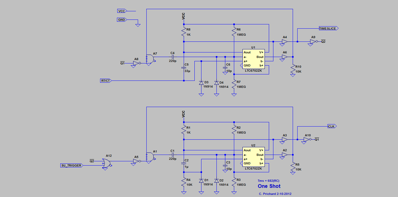
Diagram suggests connection of pressure switch. Actual prototype will use NAND logic, the pressure switch pulling the resistor LOW. The one-shot pulse will then be inverted. I have two LTSPICE one-shot models. The one using a comparator, is re-triggerable. The pulse in milliseconds is approximated as equal to 682xRC. I will post the models as part of this project.
FOLDER LINK: 1SHOT LTSPICE models Using one of the jigs, I determined a time constant for one of the models, and ran simulation for a 3-minute pulse. I've made lots of models for LTSPICE, including a collection of TTL logic.
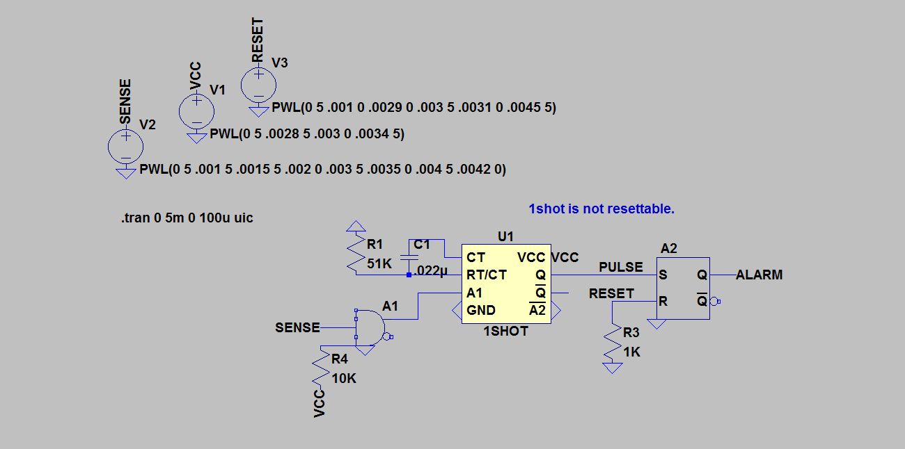
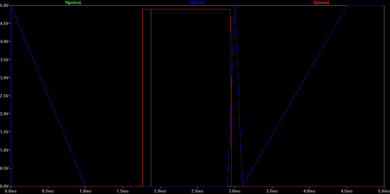
LT1013 opamp 1SHOT is not retriggerable. I can reset the alarm, but another trigger does not produce a pulse from the 1SHOT. RESET can only happen with power OFF. Using the LTC6702ZK comparator it is retriggerable. I like having ability to resolve these things in simulation.
Simplification:
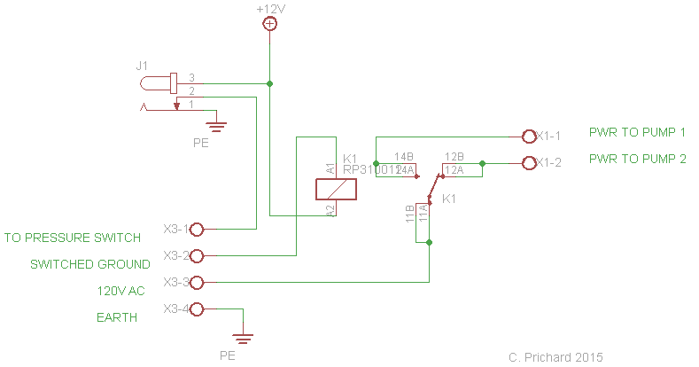
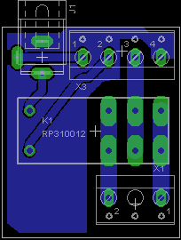
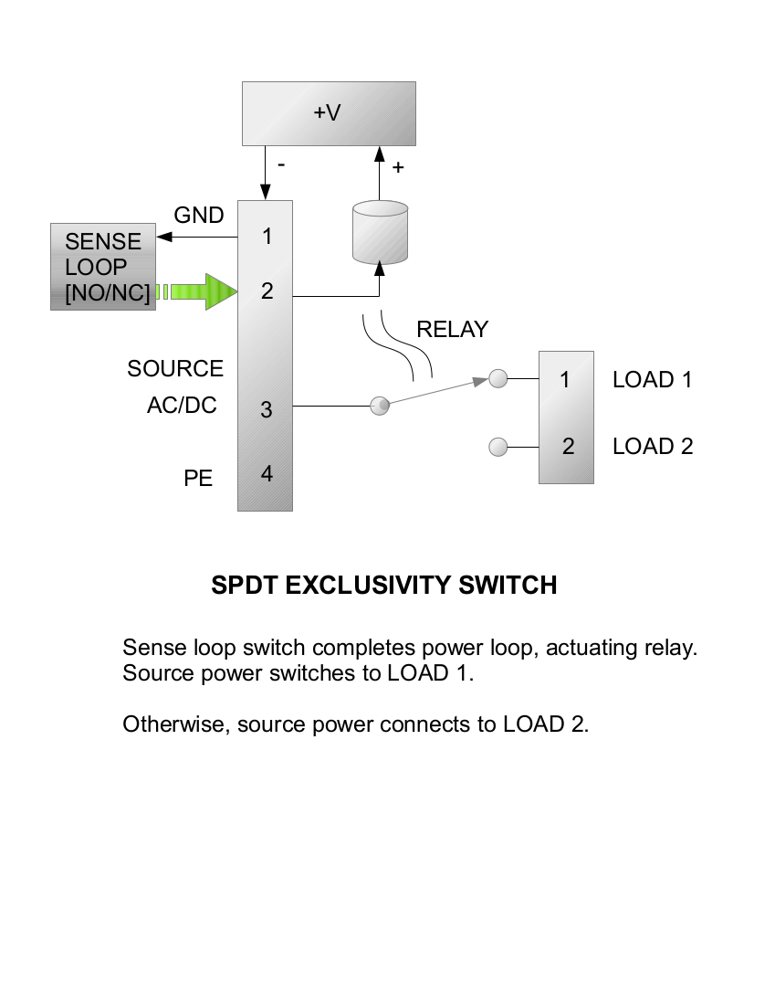
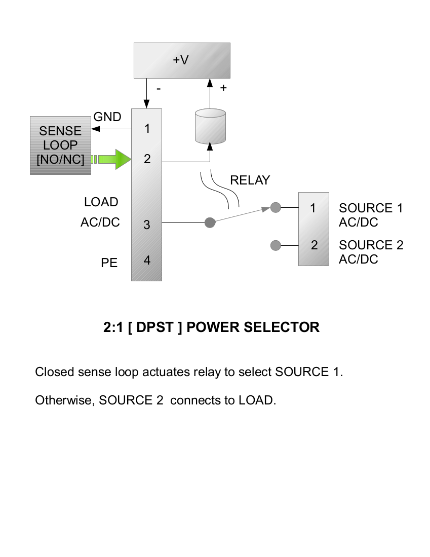
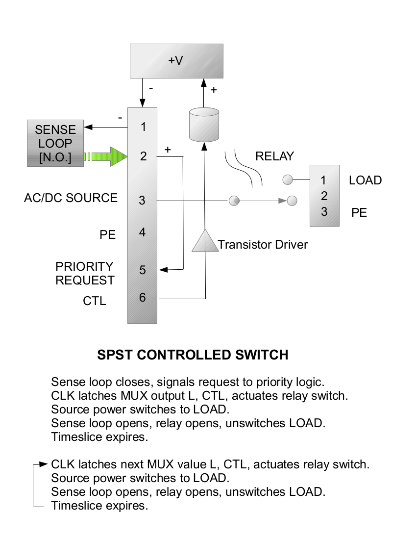
Pins 1, 2 are used to loop the ground connection from the 12V power input to pressure switch contacts, and back to the relay. When the pressure switch closes, and relay is energized, AC power switches from Pin 3 to PUMP 1 connected to X1 - 1.
The device, approximately 1.5x1.5 inches can be encapsulated with pigtails, or made in such a way it can be mounted on/in an electrical enclosure commonly used in construction.
A version with softstart may be useful, guaranteeing the relay cannot operate for a period of time, or until an input enable signal is received.
I could call it an "EXCLUSIVITY POWER SWITCH" or "NON-CONCURRENCY SWITCH." The switch shown is rated for 16 amps.
This is progress, a vantage point offering a chance to prototype, consider performance, and possible enhancements: an enable input, soft start, 1-shot timing pulse, 5-volt logic version, Arduino interface, and others...
6-23-2015 C. Prichard
Holdoff circuit delays switching at startup.
I have done LTSPICE simulation.
Circuit prevents switching at power-on. Not sure if 3906 driver is adequate. I must find this relay and read spec. The power plug pinout is also questionable... The board is 1x2 approximate. 555 monostable may be more elegant, though a schmitt buffer provides necessary hysterisis in the power-on delay (IC1A.) Sense from pressure switch is ANDED with delay of IC1A. After initial delay, switching articulated by the pressure switch can occur any time, without any logic combination. I have the delay set to about three minutes, allowing the septic pump to complete its task. Normally, a low-power delay will precede switching the well pump, allowing the inverter to recover somewhat from a 30% maximum load before running a slightly heavier load. This may extend the life of the inverter...
Another, more complex version will consider possibility of switching a compressor, or other inductive loads at startup. Objective may be to create a sequence, and switching EACH inductive load independently via an SPST switch. Thus, four loads will require four switches. However, after initial startup additional logic is required to then prioritize switching, preventing more than one switched inductive load. This may not be too unreasonable. I may have finally found a serious application for my priority multiplexing logic. This all has serious application with automation that senses lightning strikes.
It will be interesting to put the larger design together, designing each switch to be controlled by prioritizing logic, and its own sense loop. Switch modules will be identical, except for possible relay ratings. A light, DC switch may have applications... Design phase becomes easier, looking to create a simple SPST module with sense loop input, and a CTL logic signal. Each module will send a signal to the priority multiplexor as a request to switch the relay.
With several inductive loads, it becomes desirable to prevent concurrent switching that can stress components, and reduce life of the inverter.
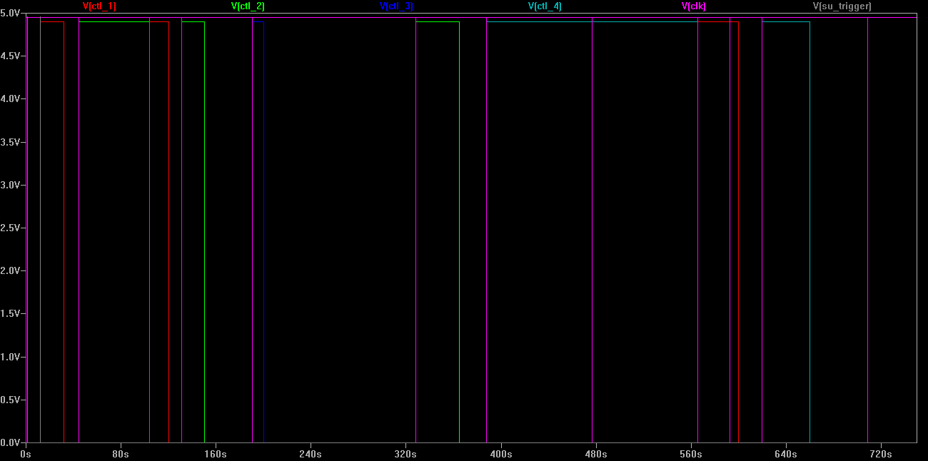
Above shows 7477 latch clocking between variable timeslices. I use a 2-phase, retriggerable monostable concoction.

PMUX can be a PAL. I am creating the entire schematic to build with discrete components. Monostables can be the 74123...
Below is the wonderful 2-phase LTSPICE concoction model...
I'm working on a DUMMY sense loop on the relay card. It will probably use a long delay to keep the PRQ from the PMUX input. I need to retrigger the delay with a signal from the main logic, clearing a capacitor. Startup can be a little tricky in the simulation. The 74123 has CLR.
DUMMY CARD BLOCK DIAGRAM
Intent of this device is to DUMMY recurring latched PRQ to the PMUX. TIMESLICE will expire and the DUMMY card cannot reissue the PRQ without a delay. This will be useful for devices such as a septic pump, which can perform its task in thirty seconds, and be given a low priority TIMESLICE every twenty minutes.
I realized I might try using the 1shot output without a latch. Then it was pretty easy to determine the combination of DL and CLK would give me the needed reset trigger to start the delay.
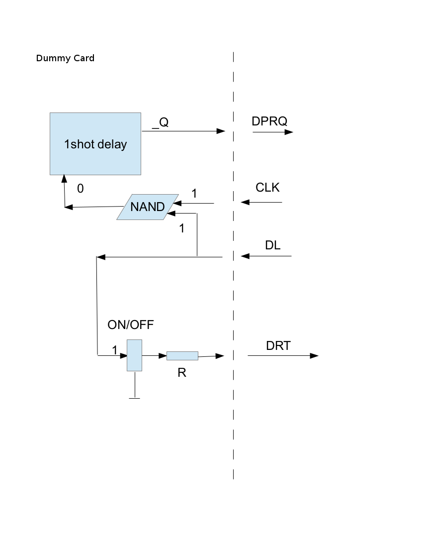
This card is crucial to the Load Center.
DL and CLK signals NAND to retrigger the DELAY. I realized it possible to simplify, and do it without latching. I use the inverted 1shot output as the DPRQ signal. A RESET and SU trigger is added to the input. Q1 supplies current through R9 to the RT connection.
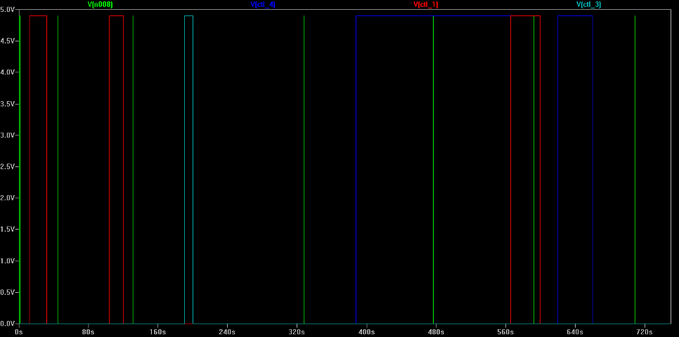
Simulation works! I created a model of the dummy card and deleted voltage signal I had used for PRQ_4. The dummy card model creates the signal in the new simulation. It requests a PRQ, and waits while higher priorities are selected in the PMUX. Nothing else has changed in the simulation.
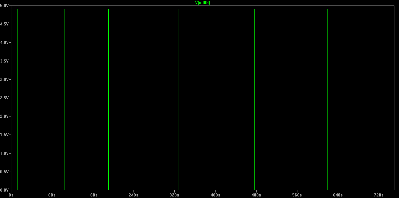
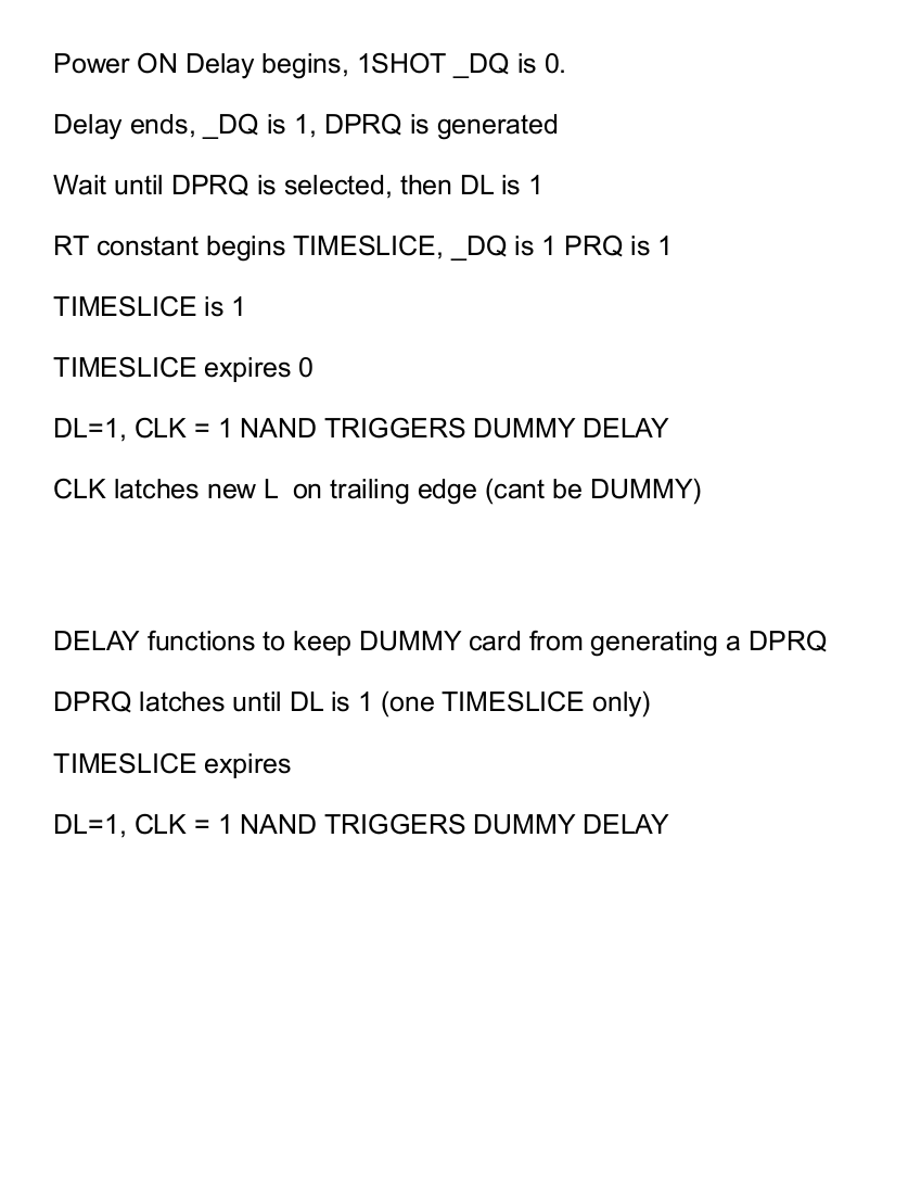
Graph shows DPRQ at 150 seconds. It is not selected in PMUX until 380 seconds. The TIMESLICE expires, and during the subsequent delay no other PRQ is selected. A second DPRQ is generated to the PMUX input, but another clock is needed to latch DL.
The model appears to be working properly. After a delay (520 to 680,) the next DUMMY PRQ is generated.
From this simulation, I may have determined it is optimal to detect when PMUX PRQ input is void and use a short delay.
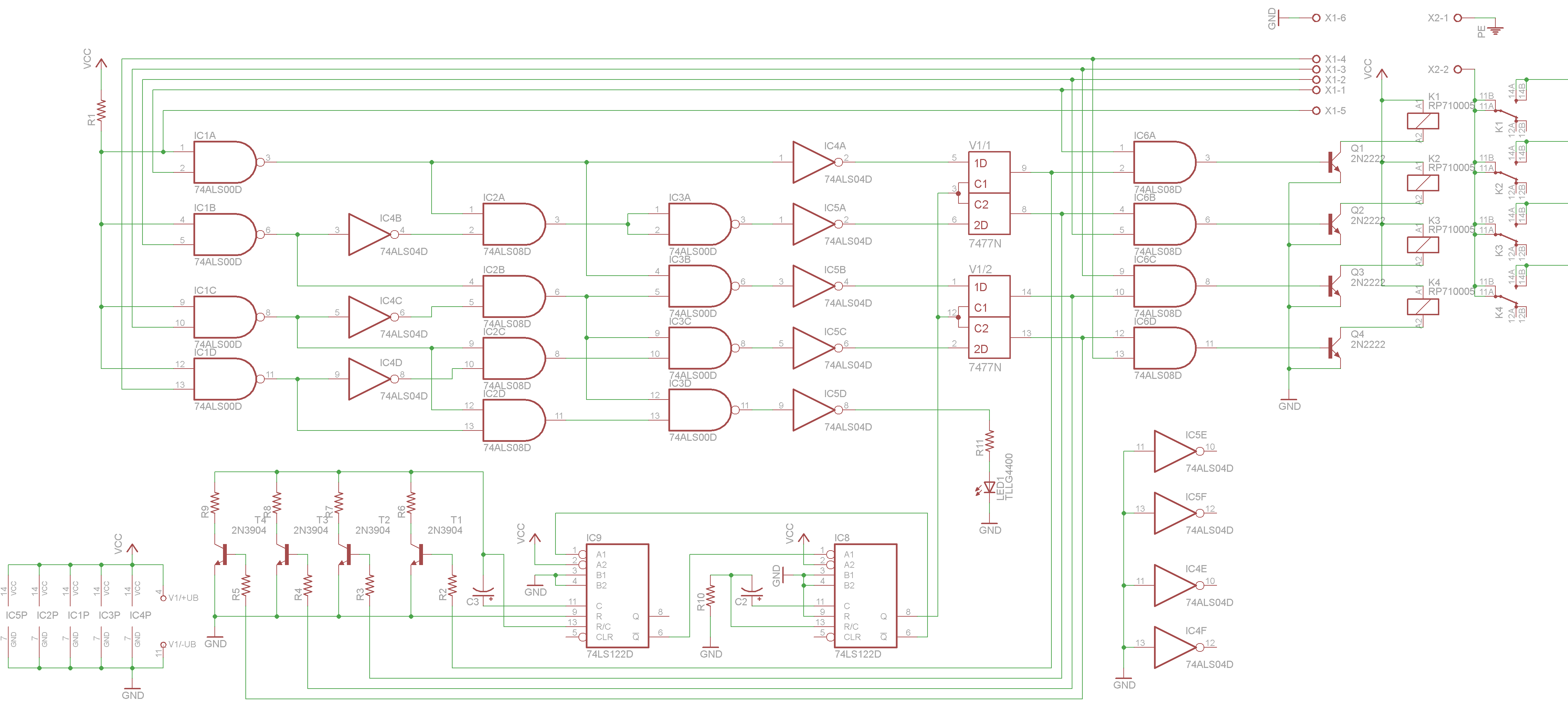
Schematic now reveals prioritizing logic to the world.
Discrete implementation as below is possible. I threw in the relays to gain perspective. Actual Schrack SP relays of same footprint are available. Off-board is the sense input conditioning, DUMMY PRQ generation ... a power supply input is also lacking. I could actually prototype this and solder edge contacts for 120V switched hot connections.
This drawing is about perspective. It is 3x4 (Free Version.) A 4x6 would do nicely.
Logic can be implemented in an older 18 or 22 pin PAL available from ATMEL. It may be possible take latched L values back into another set of AND gates, reducing the top row of IC to a single component. THAT makes this board much less costly to assemble.
A quick scan of marketplace shows nothing remotely similar to this concoction in the market, anywhere. To my knowledge, it is unique in this world.
Revised DUMMY CARD BLOCK DIAGRAM, created DC LTSPICE model, created simulation.
C. Prichard LAST UPDATED 7-14-2015