 marvin
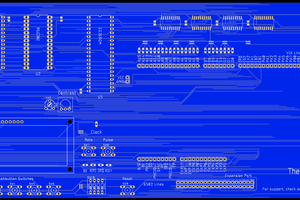
small-scope is composed of three components:
The shield shapes the signal. The arduino itself captures the data and sends it to PC, which then displays the data in software.
To test the firmware and software, the shield can be replaced with a few wires and a pot (or even nothing at all).


 Josh Kittle
 Flavio
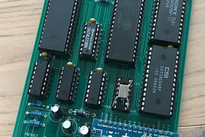
 Ruud van Falier
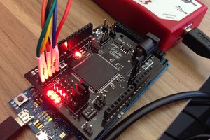
 technolomaniac
I looked everywhere for a 800k resistor in 1% that didnt require me to buy 5000 milspec units from digikey, so I am using a 330k and a 470k in series for a measured resistance of 799k, so within 1%. but the 130pf caps have been a problem, as I can't seem to locate one that isn't smd or $3.00 a piece from a radio-repair site. I hav etched the board and am building, will post pictures when finished. Awesome Design! I can't wait to finish it and test it out!
edit- I also changed the layout a bit, as I didn't have a pcb-mount BNC so I am using an RCA jack to test.