 Henryk Plötz
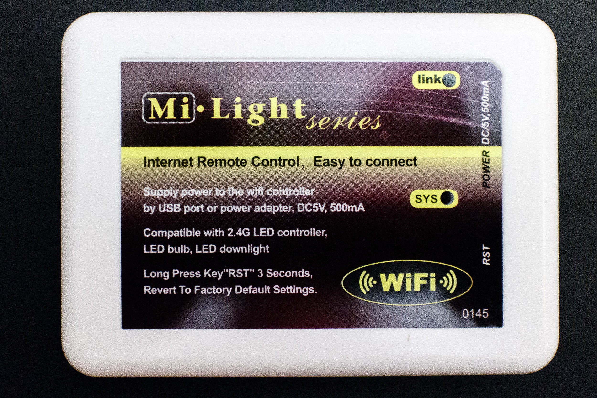
I also wanted to sniff the communication between the micro controller and radio IC, but couldn't get the case of the remote control open. At the next opportunity I brought the Mi-Light Wi-Fi controller with me and got that open more or less easily:
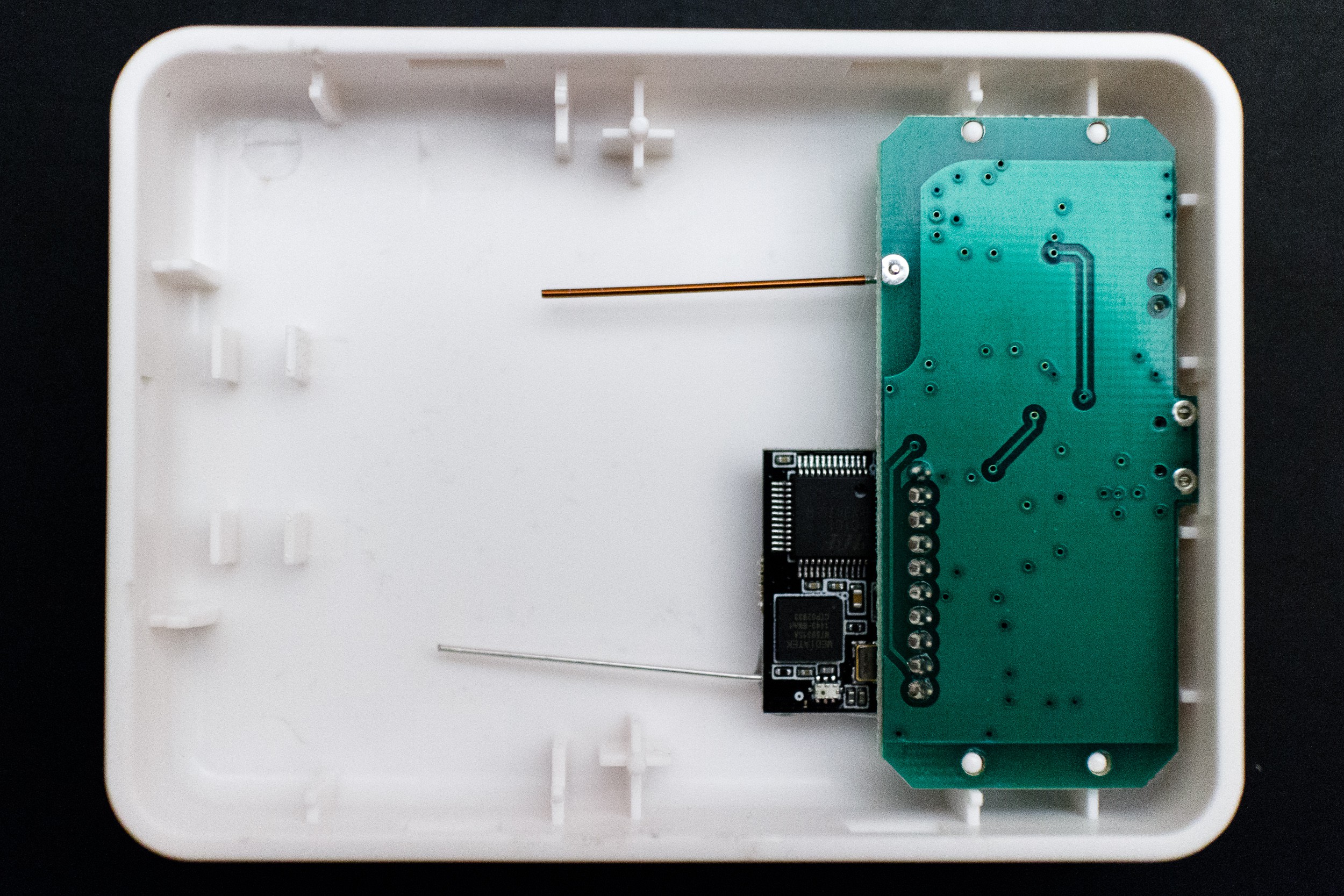
Inside wasn't much: a main board and, as I'd read before in the openhab group, a Wi-Fi daughter board connected to that, both with simple wire antennas.
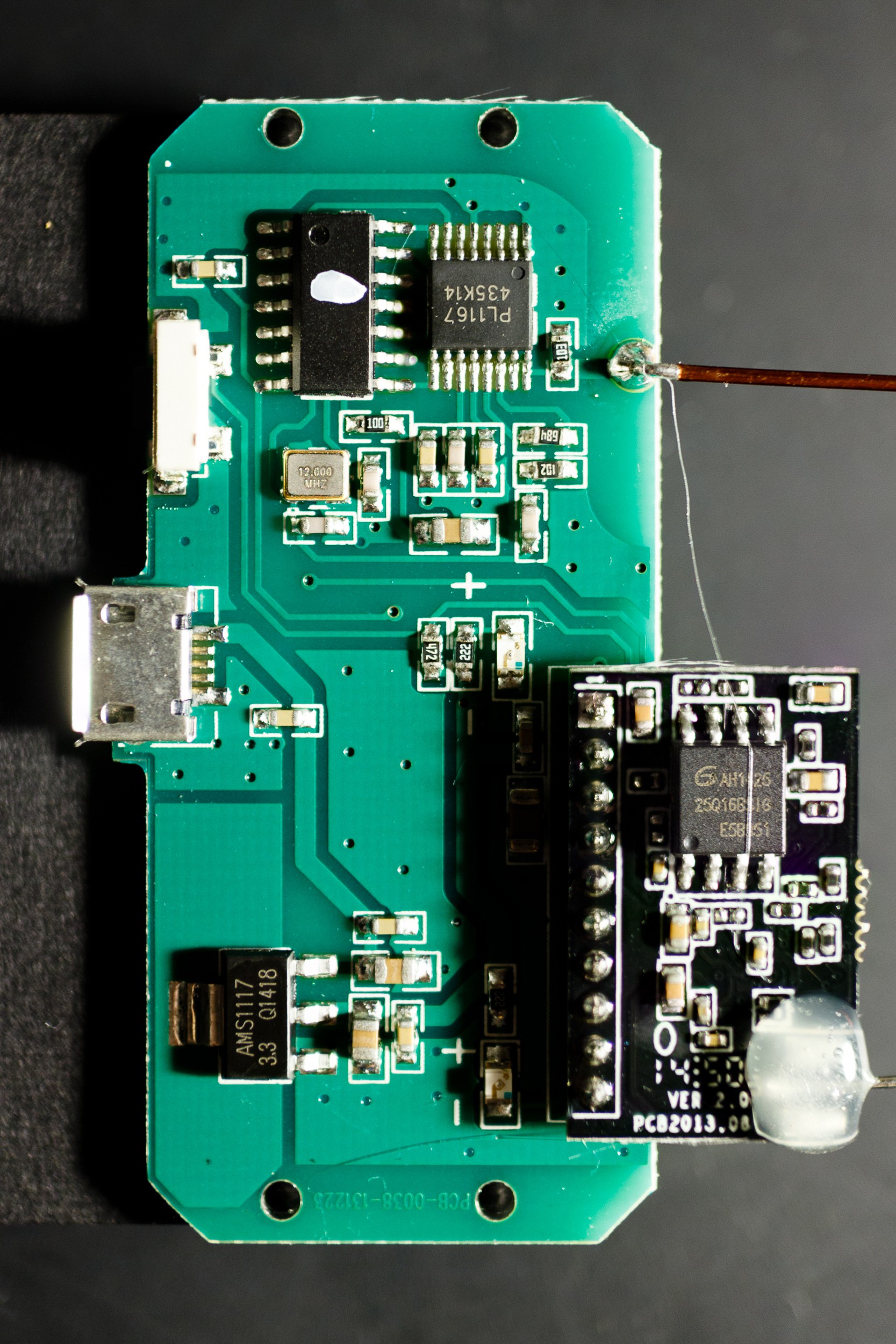
I knew that the connection between the boards wasn't interesting, since it only contains an UART with the command set I already know. I also know that that command set isn't related (in any obvious way) to the on-air protocol. That leaves me with a conclusion: The unmarked chip in the top left must be a microcontroller that implements the actual protocol and transmits commands to the PL1167 chip to the right of it. The PL1167 chip's leads seemed a little small to try to connect a logic analyzer, so instead I connected it to the microcontroller. I didn't know the pinout (except that center right is ground), so I just connected probes at random, hoping to catch something interesting (the probe at the bottom of the image is connected to ground).
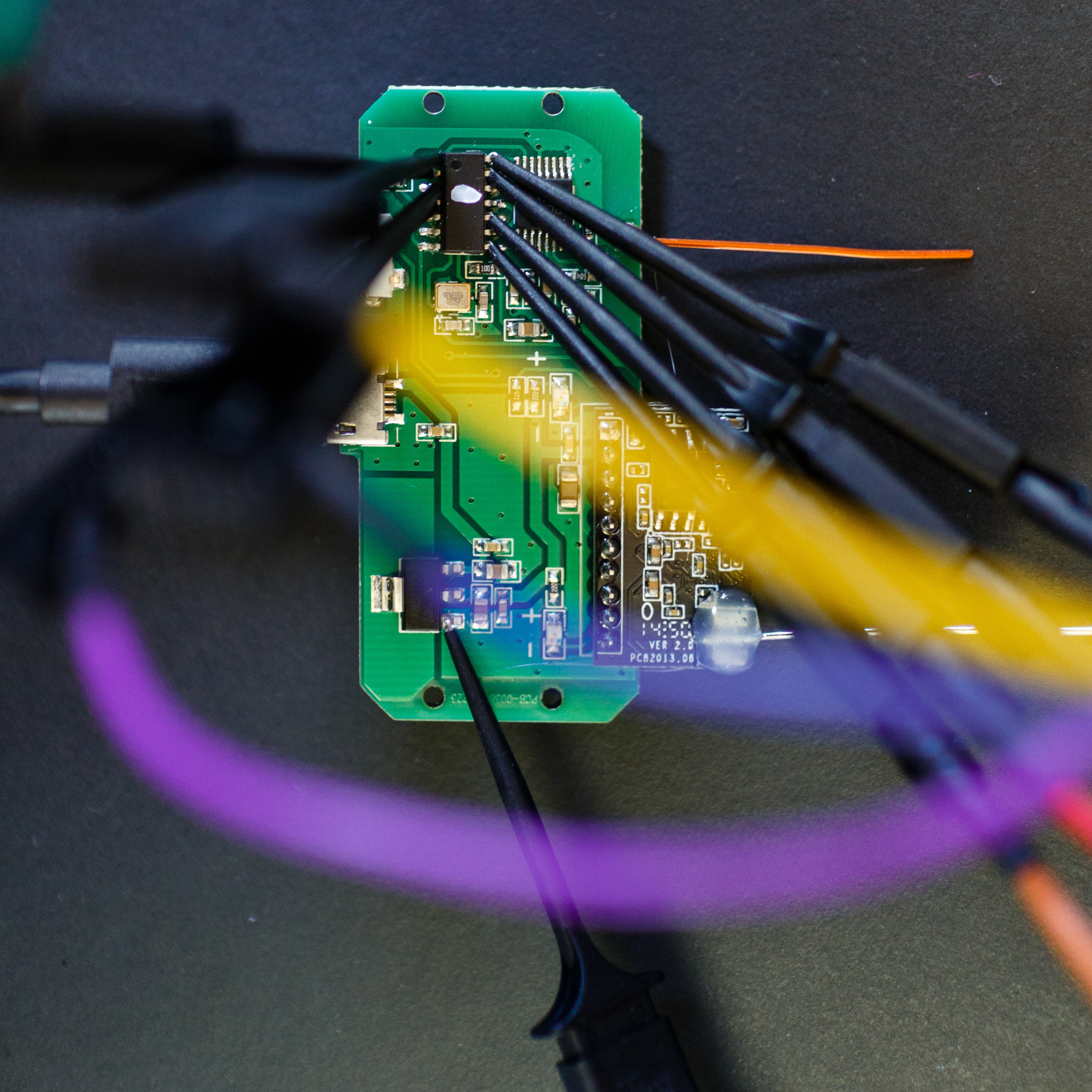
Counting counter clockwise from the marking on the microcontroller I got probes onto 1, 2, 3, 4, 8, 10, 13, and 14. I was using a Saleae Logic with their beta software for Linux (for some reason the 'stable' version would crash rather reliably). I also had the RF receiving set up, though it turned out that I didn't really need it:

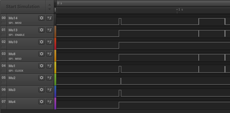
And yep, sure enough, I got all four wires required for SPI among my sniffed traces, and can see some action when the device boots:
I had to play with the SPI settings to get this right (CPOL=0, CPHA=1), but it matches up with what the data sheet told me. Here you can see it writing the "Register Optimum Values" from the user manuals right after boot:
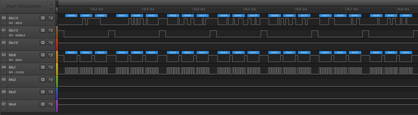
I exported the data from the Logic software as a CSV file and wrote a small python tool to decode and interpret the data, this is what happens on boot:
  1.17814875: Write reg  0 -> 6F E0
  1.17824850: Write reg  1 -> 56 81
  1.17834825: Write reg  2 -> 66 17
  1.17844775: Write reg  4 -> 9C C9
  1.17854750: Write reg  5 -> 66 37
  1.17864725: Write reg  7 -> 00 4C channel 76 (2478)MHz
  1.17874700: Write reg  8 -> 6C 90
  1.17884675: Write reg  9 -> 48 00
  1.17894650: Write reg  A -> 7F FD
  1.17904625: Write reg  B -> 00 08
  1.17914575: Write reg  C -> 00 00
  1.17924550: Write reg  D -> 48 BD
  1.17934525: Write reg 16 -> 00 FF
  1.17944500: Write reg 17 -> 80 05
  1.17954475: Write reg 18 -> 00 67
  1.17964450: Write reg 19 -> 16 59
  1.17974425: Write reg 1A -> 19 E0
  1.17984375: Write reg 1B -> 13 00
  1.17994350: Write reg 1C -> 18 00
  1.18004325: Write reg 20 -> 48 00 preamble length: 3 bytes, syncword length: 32 bits, trailer length: 4 bits, data type: NRZ, FEC: None
  1.18014300: Write reg 21 -> 3F C7
  1.18024275: Write reg 22 -> 20 00
  1.18034250: Write reg 23 -> 03 00
  1.18044225: Write reg 28 -> 44 02
  1.18054175: Write reg 29 -> B0 00 CRC on, first byte is length, FW_TERM_TX, initial CRC data: 00
  1.18064150: Write reg 2A -> FD B0
  1.18074125: Write reg 2B -> 00 0F
  1.39462075:  Read reg  0 -> 6F E0
  1.39473375:  Read reg  1 -> 56 81
  1.39484675:  Read reg  2 -> 66 17
  1.39495975:  Read reg  4 -> 9C C9
  1.39507300:  Read reg  5 -> 66 37
  1.39518600:  Read reg  7 -> 00 4C channel 76 (2478)MHz
  1.39529900:  Read reg  8 -> 6C 90
  1.39541200:  Read reg  9 -> 48 00
  1.39552525:  Read reg  A -> 7F FD
  1.39563825:  Read reg  B -> 00 08
  1.39575125:  Read reg  C -> 00 00
  1.39586425:  Read reg  D -> 48 BD
  1.39597725:  Read reg 16 -> 00 FF
  1.39609050:  Read reg 17 -> 80 05
  1.39620350:  Read reg 18 -> 00 67
  1.39631650:  Read reg 19 -> 16 59
  1.39642950:  Read reg 1A -> 19 E0
  1.39654250:  Read reg 1B -> 13 00
  1.39665575:  Read reg 1C -> 18 00
  1.39676875:  Read reg 20 -> 48 00 preamble length: 3 bytes, syncword length: 32 bits, trailer length: 4 bits, data type: NRZ, FEC: None
  1.39688175:  Read reg 21 -> 3F C7
  1.39699475:  Read reg 22 -> 20 00
  1.39710800:  Read reg 23 -> 03 00
  1.39722100:  Read reg 28 -> 44 02
  1.39733400:  Read reg 29 -> B0 00 CRC on, first byte is length, FW_TERM_TX, initial CRC data: 00
  1.39744700:  Read reg 2A -> FD B0
  1.39756000:  Read reg 2B -> 00 0F
  1.39767075: Write reg  7 -> 00 00 channel 0 (2402)MHz
  1.39776325: Write reg  7 -> 00 00 channel 0 (2402)MHz
  1.39785550: Write reg 34 -> 80 80 clear FIFO TX, FIFO write pointer: 0, clear FIFO RX, FIFO read pointer: 0
  1.39794525: Write FIFO: 06 00 00 00 00 00 00
  1.39819100: Write reg  7 -> 01 00 start TX, channel 0 (2402)MHz
And this is what happens when I send the "ALL ON" command every second:
  0.65326000: Write reg  7 -> 00 00 channel 0 (2402)MHz
  0.65336250: Write reg 24 -> 14 7A syncword 0: 147A
  0.65346500: Write reg 27 -> 25 8B syncword 3: 258B
  0.65357250: Write reg  7 -> 00 00 channel 0 (2402)MHz
  0.65367625: Write reg 34 -> 80 80 clear FIFO TX, FIFO write pointer: 0, clear FIFO RX, FIFO read pointer: 0
  0.65377725: Write FIFO: 07 B8 FD 4D 00 00 01 06
  0.65408750: Write reg  7 -> 01 09 start TX, channel 9 (2411)MHz
  0.65455775: Write reg  7 -> 00 00 channel 0 (2402)MHz
  0.65465950: Write reg 34 -> 80 80 clear FIFO TX, FIFO write pointer: 0, clear FIFO RX, FIFO read pointer: 0
  0.65475850: Write FIFO: 07 B8 FD 4D 00 00 01 06
  0.65506275: Write reg  7 -> 01 28 start TX, channel 40 (2442)MHz
  0.65549875: Write reg  7 -> 00 00 channel 0 (2402)MHz
  0.65560050: Write reg 34 -> 80 80 clear FIFO TX, FIFO write pointer: 0, clear FIFO RX, FIFO read pointer: 0
  0.65569975: Write FIFO: 07 B8 FD 4D 00 00 01 06
  0.65600375: Write reg  7 -> 01 47 start TX, channel 71 (2473)MHz
  0.65645225: Write reg  7 -> 00 00 channel 0 (2402)MHz
  0.65655400: Write reg 34 -> 80 80 clear FIFO TX, FIFO write pointer: 0, clear FIFO RX, FIFO read pointer: 0
  0.65665300: Write FIFO: 07 B8 FD 4D 00 00 01 06
  0.65695725: Write reg  7 -> 01 09 start TX, channel 9 (2411)MHz
  0.65741375: Write reg  7 -> 00 00 channel 0 (2402)MHz
  0.65751550: Write reg 34 -> 80 80 clear FIFO TX, FIFO write pointer: 0, clear FIFO RX, FIFO read pointer: 0
  0.65761450: Write FIFO: 07 B8 FD 4D 00 00 01 06
  0.65791875: Write reg  7 -> 01 28 start TX, channel 40 (2442)MHz

[… etc …]

  1.66702425: Write reg  7 -> 00 00 channel 0 (2402)MHz
  1.66712650: Write reg 24 -> 14 7A syncword 0: 147A
  1.66722900: Write reg 27 -> 25 8B syncword 3: 258B
  1.66733675: Write reg  7 -> 00 00 channel 0 (2402)MHz
  1.66744050: Write reg 34 -> 80 80 clear FIFO TX, FIFO write pointer: 0, clear FIFO RX, FIFO read pointer: 0
  1.66754150: Write FIFO: 07 B8 FD 4D 00 00 01 07
  1.66785150: Write reg  7 -> 01 09 start TX, channel 9 (2411)MHz
  1.66832175: Write reg  7 -> 00 00 channel 0 (2402)MHz
  1.66842350: Write reg 34 -> 80 80 clear FIFO TX, FIFO write pointer: 0, clear FIFO RX, FIFO read pointer: 0
  1.66852250: Write FIFO: 07 B8 FD 4D 00 00 01 07
  1.66882675: Write reg  7 -> 01 28 start TX, channel 40 (2442)MHz
  1.66926300: Write reg  7 -> 00 00 channel 0 (2402)MHz
  1.66936475: Write reg 34 -> 80 80 clear FIFO TX, FIFO write pointer: 0, clear FIFO RX, FIFO read pointer: 0
  1.66946375: Write FIFO: 07 B8 FD 4D 00 00 01 07
  1.66976775: Write reg  7 -> 01 47 start TX, channel 71 (2473)MHz
  1.67021650: Write reg  7 -> 00 00 channel 0 (2402)MHz
  1.67031800: Write reg 34 -> 80 80 clear FIFO TX, FIFO write pointer: 0, clear FIFO RX, FIFO read pointer: 0
  1.67041725: Write FIFO: 07 B8 FD 4D 00 00 01 07
  1.67072125: Write reg  7 -> 01 09 start TX, channel 9 (2411)MHz
So, that tells me mostly what I knew already, but more precise on some points. One new information is that they don't just transmit on 2.411GHz, but also on 2.442 and 2.473, and has 40 repetitions per transmission. Well, I guess it's one way to make the communication seem reliable. This likely means that the bulbs constantly hop between receiving on these three frequencies.
I also now know in detail how the on-air packet is constructed and can apply this knowledge towards an independent implementation.
Discussions
Become a Hackaday.io Member
Create an account to leave a comment. Already have an account? Log In.
Impressive work !
nRF24L01 uses GFSK too. This is very worth giving a try !
Are you sure? yes | no