Close
0%
0%

Character LCD Controller

Parallel Character LCD controller with UART and I2C interfaces.

Similar projects worth following
Character LCD displays are kind of a pain to work with. They require a number of GPIO pins, and a fair amount of babysitting to deal with timing, as the controller chips are pretty slow. This project converts the parallel LCD interface to a UART or I2C interface. Signals are in place to support an SPI interface if desired (and coded). There are 4 parallel input bits with ESD protection for a simple user interface.

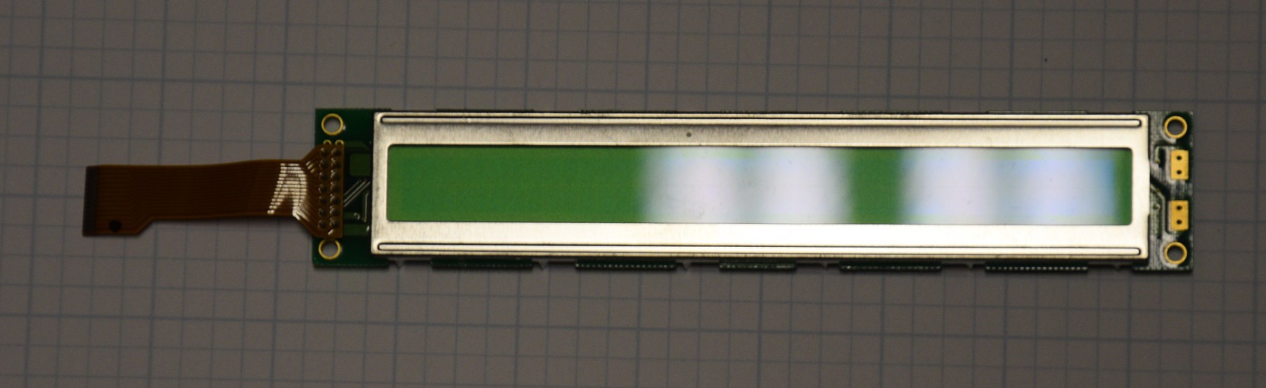
A few years ago, I picked up a box full of new, 40 Character x 2 Line character LCD displays at a hamfest for an excellent price.  Unfortunately, they have a short FFC cable pre-attached. The 0.1" two row connectors would be easier to deal with. I have removed the FFC cables from several of these displays and used them in projects. I created an adapter to go from 0.1" header connectors to the proper FFC connector, and that was much easier than removing the FFC cable, but the FFC cable is still pretty short.

40 Character x 2 Line LCD Display Module

Using the 8 bit version of the parallel interface to the display requires 11 GPIO signals that are not always available on an MCU project. A small MCU backpack board that has a serial or I2C interface would reduce the problems with hogging GPIO signals.  It would also be an option to add inputs for a simple user interface.

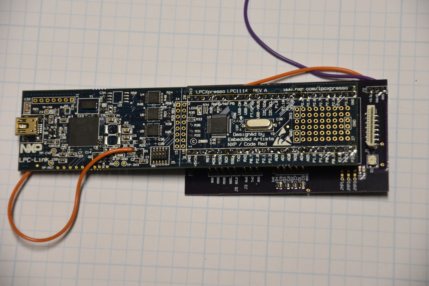
The LCD displays are 5 Volt displays, so the microcontroller that drives the display should have 5V tolerant I/O signals.  I have an eval board with an NXP LPC1114 MCU (ARM M0) on it and have used that MCU on several previous projects. The LPC1114 parts are reasonably inexpensive.

LPC1114 Eval Board and the Fanout Board for SW development


There is plenty of I/O available on this part (48 pin), so I added 4 bits of parallel I/O with ESD protection to allow adding a simple user interface with up to 4 buttons or switches without hardware changes. The chip also has an ADC on it, so I picked the GPIO pins that could be configured as analog inputs or GPIO for the user input in case I wanted to digitize an analog signal instead of a digital bit.

Serial (UART) communication with the display is simple to implement, so it was a given for an interface choice. I2C would be a nice option, because a lot of my projects already have stuff on an I2C bus and the address choices that I2C offers would make it easy to control several displays if that was ever needed. The LPC1114 chip has a SPI interface on it, so I included connections for it too.

To simplify software development, I laid out a small 2 layer board that would fan out the eval board to external connectors. Each of the the communications buses, the GPIO (user and display), and power were routed on the fanout board.

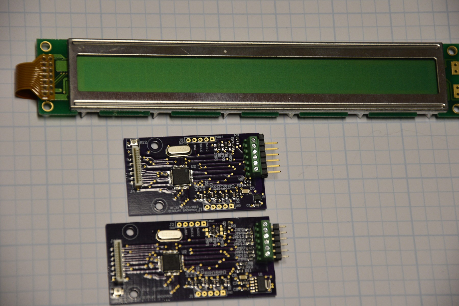
After the initial firmware was progressing, I laid out a small 4 layer board with the minimum components to support the MCU, the ESD protection parts for the GPIO and a voltage regulator to feed the 3.3V MCU from the 5V display power line. At the time, I thought it would be necessary to isolate the different I/O buses, so I included jumpers to select the I/O bus and route to the screw terminal strip. The resulting board was a little larger than I wanted, but I figured that getting a usable board for further software testing would be good, so it was sent out to OSH Park for fabrication.

The firmware was mostly done by the time the 4 layer board came back. I populated the new boards, and everything fit. It turned out that the orientation of the FFC connector for the display was inconvenient, resulting on the backpack board components facing the LCD board with its components and mounting tabs. The board powered up and worked as expected. To test the idea that leaving the unused communications options disabled, would not interfere with the functioning option, I populated all of the I/O selection jumpers and tested it. All was well.

I wanted a smaller PCB for the backpack to get the cost down. I also wanted to flip the FFC connector around so that the backpack board components were away from the LCD module. I modified the existing layout, flipping the FFC connector, and replacing the I/O selection jumpers with copper. I also replaced the 3.3V regulator with a smaller one. The new board came out under 3 square inches.

Display and Rev 1.1 and 1.0 Backpack Boards

Adobe Portable Document Format - 194.96 kB - 02/20/2018 at 19:24

Preview
Download

  • Firmware

    Bharbour02/20/2018 at 19:00 0 comments

    Initially, I thought about abstracting the low level commands to the LCD module so that the host firmware would not have to know much about the display module. This abstraction would require the backpack module to know and remember what the LCD configuration data was. It did not seem worth the effort to do this abstraction, and I opted for pushing that knowledge up to the host processor. A simple command language that would not change much between the UART or the I2C interface was cooked up.

    The LCD has 2 addresses, a command address for configuration and addressing commands and a data address to accept display data. The commands look like:

    @@ Cmd N D1D2D3Dn LF

    where:

    @@ two literal characters to lead the command packet. (only used in serial mode).

    Cmd is a command code, 0=command, 1=display data, 2=system command.

    N is the number of data bytes.

    D1 D2 D3 Dn are the data bytes, 8 bit, binary.

    LF is a literal Line Feed Character to end the command (only used in serial mode).

    The I2C protocol that I implemented is very SMBus like with the command code and transaction length. The I2C mode even implements the optional packet error checking for SMBus.

    Because the I2C physical layer has detectable start and stop operations, the leading "@@" and the trailing LF characters were not used in I2C mode. A multi-character async serial sequence does not really have a detectable start or stop event, so the "@@" and LF characters provide that.

    When the LPC1114 comes out of reset, it configures the clock block and enough of the GPIO to read the communication select jumpers. The value of the communication select jumpers goes into RAM and is kept until reset or power loss. After reading the jumpers, the selected interface (UART, I2C) gets its pinmux configured and initialized.

    All of the UART and I2C I/O handling is done in interrupt routines. The LCD interface is implemented in the foreground, since it is less time sensitive and may take significantly longer.

    LCD commands like clearing the display may take a long time (up to 44mS). The Hitachi LCD controller manual says that you can wait the max time for a command or you can read the command address, and it will return a busy flag until each command is done. Bidirectional data is easy on a real microprocessor data bus (which has not been seen in the wild in decades), but slightly more trouble when using GPIO bits. In order to read the busy flag, the GPIO pins need to be configured as inputs, then to write data and commands, the GPIO bits need to be configured as outputs.

    At this time, the only system command implemented is the read user I/O command that returns 1 byte with the 4 user bits in the low end.

    Code for the I2C SMBus operation was re-used from a project that I did about 8 years ago. This application is a LOT simpler that the previous one, so there was a lot of code removed and a little bit of new code.

    The UART code is mostly just interrupt driven data in and data out operations with some buffer management to not lose data while the LCD interface is active.

    Since the UART interface is handling binary data, it was necessary to write a simple tool to talk to the display module from a PC for testing. Code for the UART version was modified somewhat to create a tool for testing the I2C configuration of the backpack.

View project log

Enjoy this project?

Share

Discussions

Similar Projects

Does this project spark your interest?

Become a member to follow this project and never miss any updates