Close
0%
0%

VPN Light Switch

A Wi-Fi based LED switch to check that your VPN is running on your router and control it.

Similar projects worth following
Have you ever wanted to control your OpenVPN client daemon at the click of a button, as well as know whether it is running correctly or not from a glance? If you use this VPN Light Switch, you can do just that!

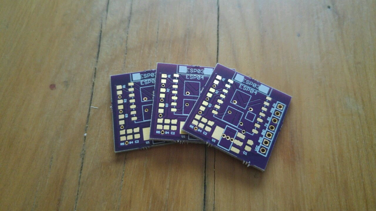
OSHPark PCBs - https://oshpark.com/shared_projects/IvtIc9f2


The OpenVPN client daemon is quite a versatile little dude. Unfortunately, if you use it on a WRT based router to enable it for all devices on your network, it can be quite difficult to control, expecially if you use devices that don't have web browers.

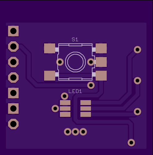
In that sense, the VPN Light Switch solves this issue by creating an easy to use interface that enables you to view your VPN status, as well as pause and resume it.

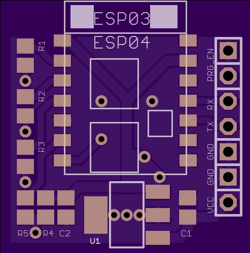
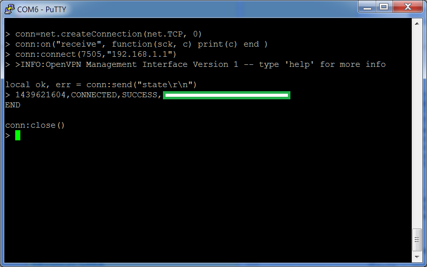
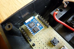
By using an ESP8266 module, the NodeLUA firmware and enabling the management interface on your VPN client daemon, you can create a very simple interface for interfacing to the daemon, in an all in one nature.

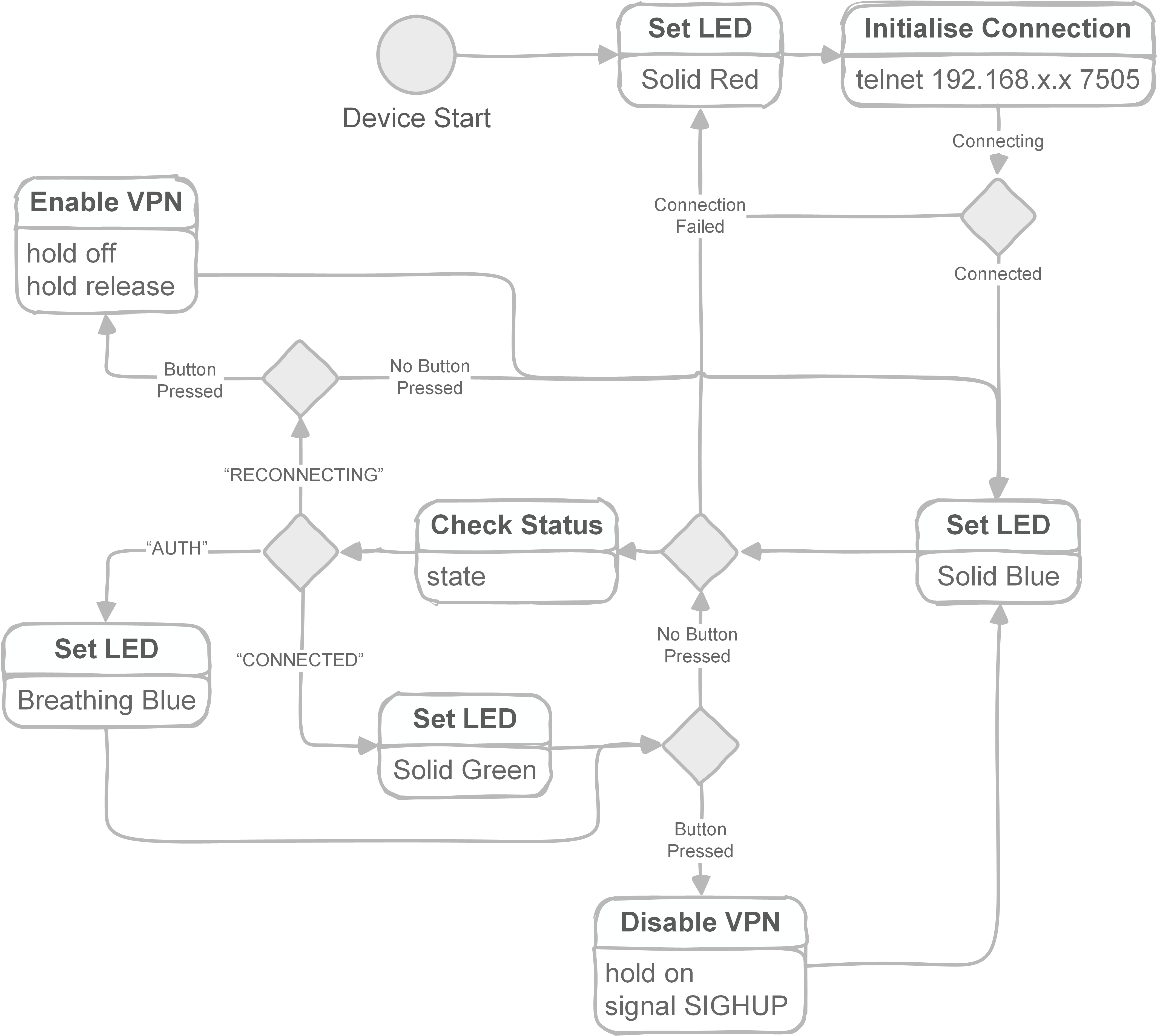
Here is a simple state machine for how the ESP module operates once connected to the Wi-Fi network that has the VPN service you want to control:

Read more »

  • 1 × Momentary Switch
  • 1 × Resistors
  • 1 × UART->USB Converter To configure the ESP module.
  • 1 × ESP8266 Module With the LUA based nodemcu firmware.
  • 1 × OpenVPN Client Daemon

View all 6 components

  • Video Demo

    Blecky01/27/2016 at 12:25 0 comments


    Red LED - VPN Disabled

    Purple LED - VPN Init

    Green LED - VPN Enabled

    Blue LED - VPN Standby (inactive)

  • Updated LUA Code

    Blecky01/27/2016 at 11:39 0 comments

    Updated init.lua for the PCB with the Osram LED:

    function vpnconnect ()
      conn=net.createConnection(net.TCP, 0)
      conn:on("receive", function(sck, c)
        if string.find(c,"CONNECTED") then
          print("Connected")
          state = 1
          gpio.write(5, gpio.HIGH) --RED
          gpio.write(6, gpio.LOW) --GREEN
          gpio.write(7, gpio.HIGH) --BLUE
        end
        if string.find(c,"RECONNECTING") then
          print("Standby")
          gpio.write(5, gpio.HIGH) --RED
          gpio.write(6, gpio.HIGH) --GREEN
          gpio.write(7, gpio.LOW) --BLUE
          state = 0
        end
        if string.find(c,"AUTH") then
          print("Auth")
          state = 1
          gpio.write(5, gpio.LOW) --RED
          gpio.write(6, gpio.HIGH) --GREEN
          gpio.write(7, gpio.LOW) --BLUE
        end
        end
      )
      conn:on("disconnection", function(sck, c)
        print("VPN Disabled")
        gpio.write(5, gpio.LOW) --RED
        gpio.write(6, gpio.HIGH) --GREEN
        gpio.write(7, gpio.HIGH) --BLUE
        connected = 0
        end
      )
    end
    
    
    function buttonpress (level)
      if triggered == 0 then
        if level == 0 then
          if connected == 1 then
            triggered = 1
            tmr.alarm(1, 200, 0, function() --debounce delay
              if state == 0 then
                conn:send("hold off\r\n hold release\r\n")
                state = 1
              else
                conn:send("hold on\r\n signal SIGHUP\r\n")
                state = 0
              end
              triggered = 0
              end
            )
          end
        end
      end
    end
    
    
    --Don't forget to associate with AP with (once off) commands:
    --wifi.setmode(wifi.STATION)
    --wifi.sta.config("accesspointname","yourpassword")
    --wifi.sta.connect()
    --print(wifi.sta.status()) <--5 means associated
    --print(wifi.sta.getip())
    
    
    gpio.mode(4,gpio.INT)
    gpio.mode(5, gpio.OUTPUT) --RED
    gpio.mode(6, gpio.OUTPUT) --GREEN
    gpio.mode(7, gpio.OUTPUT) --BLUE
    
    --Set output low to turn on LED
    gpio.write(5, gpio.LOW) --RED
    gpio.write(6, gpio.HIGH) --GREEN
    gpio.write(7, gpio.HIGH) --BLUE
    
    
    connected = 0
    state = 0
    triggered = 0
    
    
    gpio.trig(4, "down", buttonpress)
    
    
    tmr.alarm(0, 1000, 1, function()
      if connected == 0 then
        vpnconnect()
        conn:connect(7505,"192.168.1.1")
        connected = 1
      end
      if connected == 1 then
        conn:send("state\r\n")
      end
      end
    ) 

  • PCBs Arrived

    Blecky12/30/2015 at 02:05 0 comments

    PCBs have arrived. Just waiting on some more ESP8266 modules.

  • OSHPark PCB

    Blecky12/03/2015 at 04:17 0 comments

    You can now order 3 of the PCBs from OSHPark for $4.90!:

    https://oshpark.com/shared_projects/IvtIc9f2

    The bill of materials is as follows:

    Part Value         Device        Package     Description                   
    C1   0.1uF Ceramic C-EUC0805     C0805       CAPACITOR, EU symbol    
    C2   22uF Tantalum C-EUC0805     C0805       CAPACITOR, EU symbol    
    JP1  2.54mm        PINHD-1X2     1X02        PIN HEADER                    
    JP2  2.54mm        PINHD-1X3     1X03        PIN HEADER                    
    JP3  2.54mm        PINHD-1X2     1X02        PIN HEADER                    
    LED1 GM5WA94310A   GM5WA94310A   GM5WA94310A Chip LED RGB                  
    R1   Blue LED      R-EU_R0805    R0805       RESISTOR, EU symbol     
    R2   Red LED       R-EU_R0805    R0805       RESISTOR, EU symbol     
    R3   Green LED     R-EU_R0805    R0805       RESISTOR, EU symbol     
    R4   10K           R-EU_R0805    R0805       RESISTOR, EU symbol     
    R5   100Ohm        R-EU_R0805    R0805       RESISTOR, EU symbol     
    S1   SKHMPSE010    TACT Switch   SKHMPXE010  6.2X6.5mm 
    ESP  ESP8266       ESP8266       ESP-03      ESP8266 Wifi module  
    U1   MIC5209-3.3YS MIC5209-3.3YS SOT223      LDO REGULATOR

    You will need to pick R1,2,3 to suit the LED you order as this can change. Please see the datasheet of the LED when ordering. The power supply is 3.3V.

    With the MIC5209-3.3YS regulator you can have an input voltage of 3.3V to 16V and it has reverse input voltage protection (the regulator shuts off safely)!

    Update:

    It turns out the GM5WA94310A LED is obselete, as is the SKHMPSE010. Suitable replacements for these are:

    Osram Opto LRTB GFTM - http://docs-europe.electrocomponents.com/webdocs/0e24/0900766b80e2426e.pdf

    APEM DTSM644RV - http://docs-europe.electrocomponents.com/webdocs/0642/0900766b80642d5a.pdf

    If using the Osram Opto, appropriate resistors are (note the designations have changed too):

    R1   Red  LED      R-EU_R0805    R0805       RESISTOR, EU symbol, 47ohm     
    R2   Green LED     R-EU_R0805    R0805       RESISTOR, EU symbol, 6.8ohm     
    R3   Blue LED      R-EU_R0805    R0805       RESISTOR, EU symbol, 22ohms


  • PCB Design

    Blecky10/10/2015 at 10:49 0 comments

    I'll soon have these made up and tested. It also doubles as an all purpose no purpose ESP board. The board itself is 1"x1" so you can order three of them from OSHPark for $5 including shipping.

  • Prototype Video

    Blecky08/15/2015 at 12:53 0 comments

    In this video I test the LED and button operation in two separate steps. This is testing the LUA code and is completely functional.

    Unfortunately, as there are limited GPIO pins on the ESP01 module, when testing the buttons, I disable one of the LEDs.

    Once I break out some more GPIO pins from the module, I will finalise the code to perform as per the state machine.

  • VPN Light Switch LUA Script

    Blecky08/15/2015 at 08:54 0 comments

    Here is some code to monitor the status of the VPN server. The RGB LEDs are common anode, with the anode connected to 3.3V (and a 100Ohm resistor on each leg connected to GPIO). The ESP module sinks the current:

    LED on - gpio.write(3, gpio.LOW)
    LED off - gpio.write(3, gpio.HIGH)
    This is so the modules still boot without going into bootloader mode, while keeping the resistor values quite small (brighter LEDs).

    Unfortunately because the ESP01 module only has two GPIOs, it is difficult to add both button and LED functionality at the same time. I will break these connections out later. But for the moment, the button is connected to GPIO 3 and the LED to GPIO 4.

    The button is connected as follows:

                             VCC                  
                            +-+-+                 
                              |                   
                              |                   
                            +-+-+                 
                            |   |                 
                            |10K|                 
                            |   |                 
                            +-+-+                 
                              |                   
                              |                   
               +-------+      |                   
    GPIO ------+  100  +------+                   
               +-------+      |                   
                              +                   
                               \  Switch          
                                \                 
                              +                   
                              |                   
                            +---+                 
                             +-+                  
                              +                   
                             GND
    

    The code:

    function vpnconnect () 
      conn=net.createConnection(net.TCP, 0) 
      conn:on("receive", function(sck, c) 
        if string.find(c,"CONNECTED") then 
          print("Connected") 
          state = 1 
    	  --gpio.write(3, gpio.HIGH)
          gpio.write(4, gpio.LOW) 
        end 
        if string.find(c,"RECONNECTING") then 
          print("Standby") 
    	  --gpio.write(3, gpio.HIGH) 
    	  gpio.write(4, gpio.HIGH)
          state = 0 
        end 
        if string.find(c,"AUTH") then 
          print("Auth") 
          state = 1 
    	  --gpio.write(3, gpio.LOW) 
          gpio.write(4, gpio.LOW) 
        end 
        end 
      ) 
      conn:on("disconnection", function(sck, c) 
        print("VPN Disabled") 
    	--gpio.write(3, gpio.LOW) 
        gpio.write(4, gpio.HIGH) 
        connected = 0 
        end 
      ) 
    end 
    
    function buttonpress (level) 
      if triggered == 0 then 
        if level == 0 then 
          if connected == 1 then 
            triggered = 1 
            tmr.alarm(1, 200, 0, function() --debounce delay 
              if state == 0 then 
                conn:send("hold off\r\n hold release\r\n") 
                state = 1 
              else 
                conn:send("hold on\r\n signal SIGHUP\r\n") 
                state = 0 
              end 
              triggered = 0 
              end 
            ) 
          end 
        end 
      end 
    end 
    
    --Currently using GPIO3 as button, all LED references commented out
    --gpio.mode(3, gpio.OUTPUT) 
    gpio.mode(3,gpio.INT) 
    gpio.mode(4, gpio.OUTPUT) 
    
    connected = 0 
    state = 0 
    triggered = 0 
    
    gpio.trig(3, "down", buttonpress)
    
    tmr.alarm(0, 1000, 1, function() 
      if connected == 0 then 
        vpnconnect() 
        conn:connect(7505,"192.168.1.1") 
        connected = 1 
      end 
      if connected == 1 then 
        conn:send("state\r\n") 
      end 
      end 
    ) 

    Note that when the VPN is in "standby", the service is still running, it just changes the IP tables so the VPN is no longer used. The service daemon will report that it is still running.

    You can use LuaLoader to save the file to the ESP module so it runs on boot.

    To stop it while testing just run:

    tmr.stop(0)
    conn:close() 

  • NodeMCU and "Telnet" Client

    Blecky08/15/2015 at 04:23 0 comments

    Here is a link to the NodeMCU firmware - https://github.com/nodemcu/nodemcu-firmware

    You can build this with the ESP toolchain (instructions on building the toolchain here). You can also use the NodeMCU flasher which has prebuilt firmware included - https://github.com/nodemcu/nodemcu-flasher

    To connect to a telnet session and send/receive, you can use the following using the socket library:

    conn=net.createConnection(net.TCP, false)
    conn:on("receive", function(sck, c) print(c) end )
    conn:connect(7505,"192.168.1.1")
    local ok, err = conn:send("state\n")
    conn:close()

  • System State Machine

    Blecky05/21/2015 at 16:03 0 comments

    Using an OpenVPN daemon (on a WRT based router for example) with the following added to the config file, you can monitor the VPN status and control it (once the service has started):

    management 192.168.1.1 7505

    If the service hasn't started, the LED will be red, indicating it needs to be started manually (via the router's web GUI for example). Once it is up and running however, it can easily be controlled via a telnet connection to port 7505.

View all 9 project logs

Enjoy this project?

Share

Discussions

alpdeon wrote 03/25/2023 at 07:24 point

Ah this something very new to me! Can you tell if we can also check out the Urban VPN that is installed backend on our Android Phone?

  Are you sure? yes | no

willieaames25 wrote 09/09/2016 at 07:34 point

Considering I messed up today trying to set up OpenVPN on kodi using this guide : https://www.bestvpnprovider.com/kodi-vpn/ , yes, that looks interested to me.

  Are you sure? yes | no

Similar Projects

Does this project spark your interest?

Become a member to follow this project and never miss any updates