 Ossum
OssumThis update has been a long time coming. Although I had roughly this leg drive system in mind since the beginning, it has proved quite fiddly to implement, as mechanical things often are.
My plan was always to use a servo converted to continuous rotation to drive the legs, this has the twofold benefit of extremely low gearing as well as including all of the driver circuitry, making it easy to control from a micro.
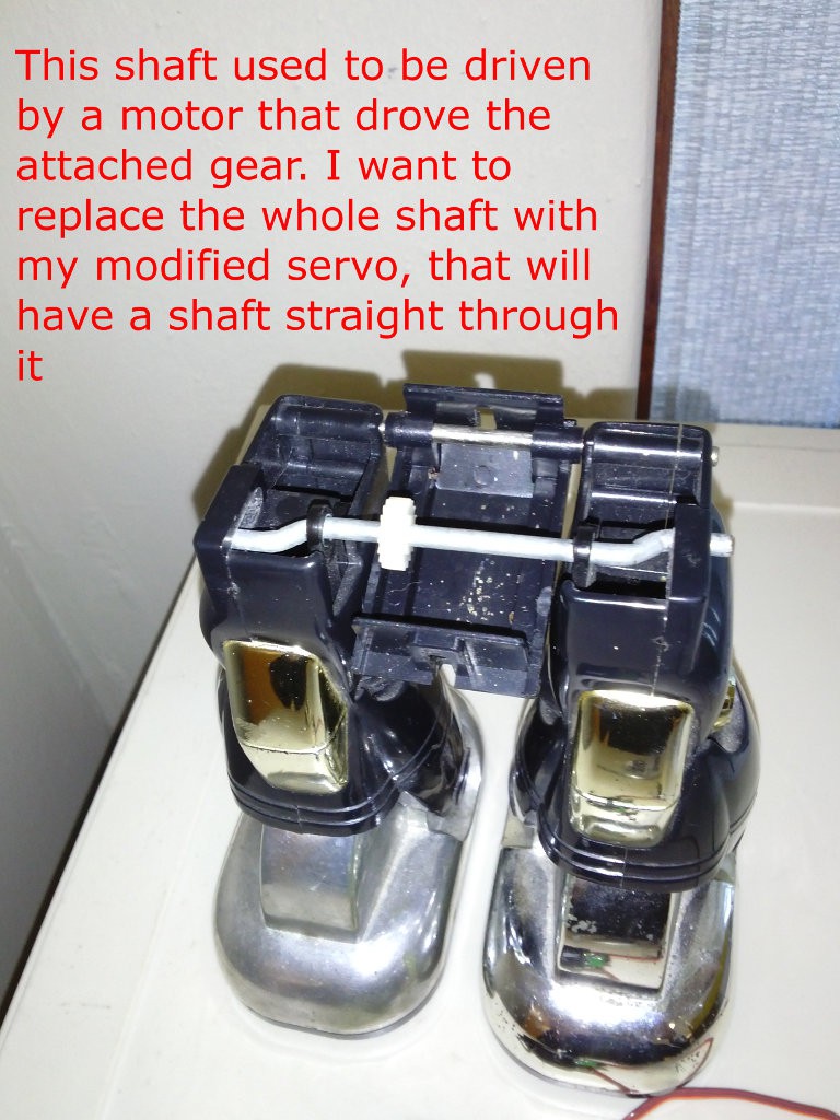
In case you are reading this log in a vacuum, here is how the leg drive axle looked before.
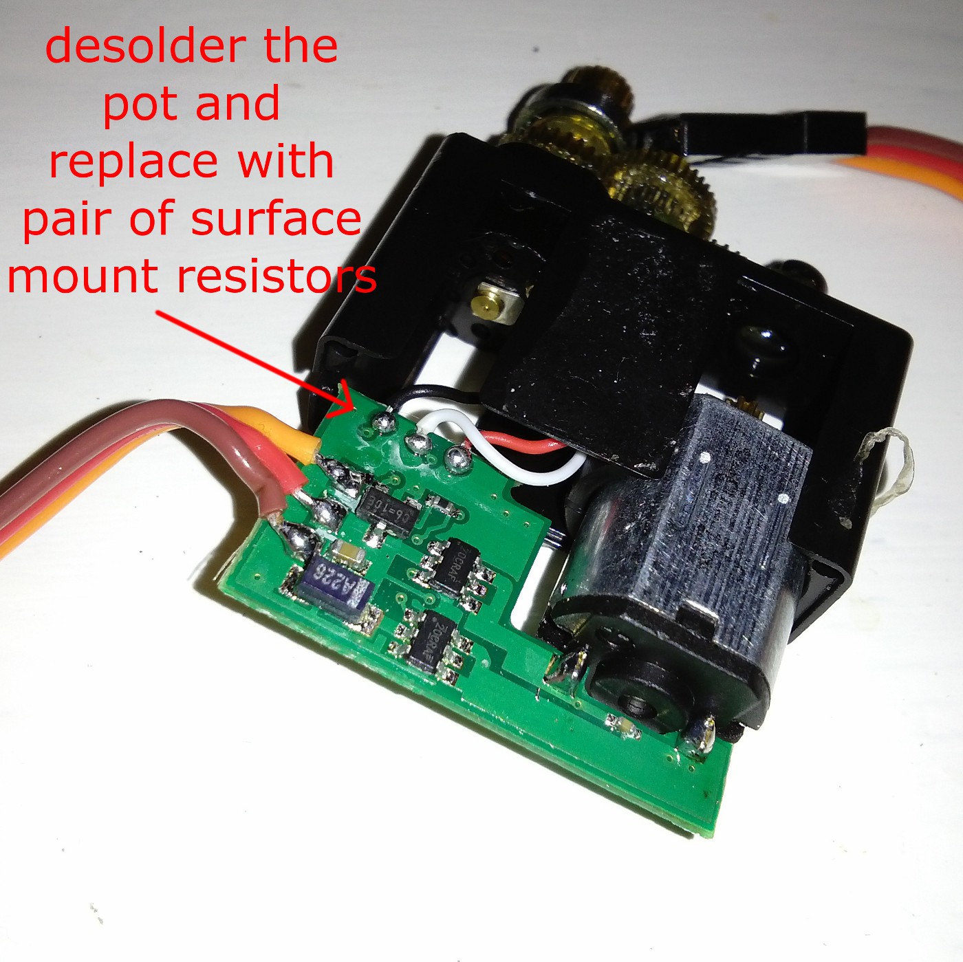
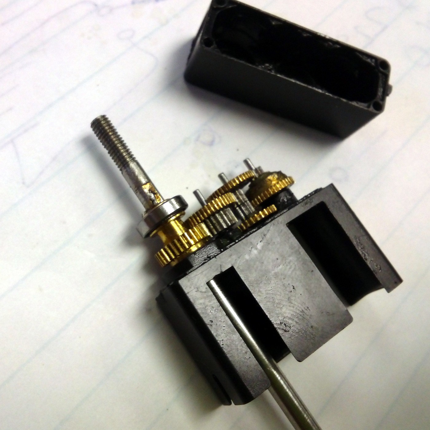
I will not delve into the conversion of the servo into continuous rotation since it is well documented (Here is one guide ), but here are a few pictures of how mine looked inside. The fortunate part of this particular servo was that the output shaft is supported on both ends by a pair of tiny ball bearings, this meant that I could remove the pot altogether (in many of the cheap plastic servos the pot's shaft is actually used as an axle for the output shaft).
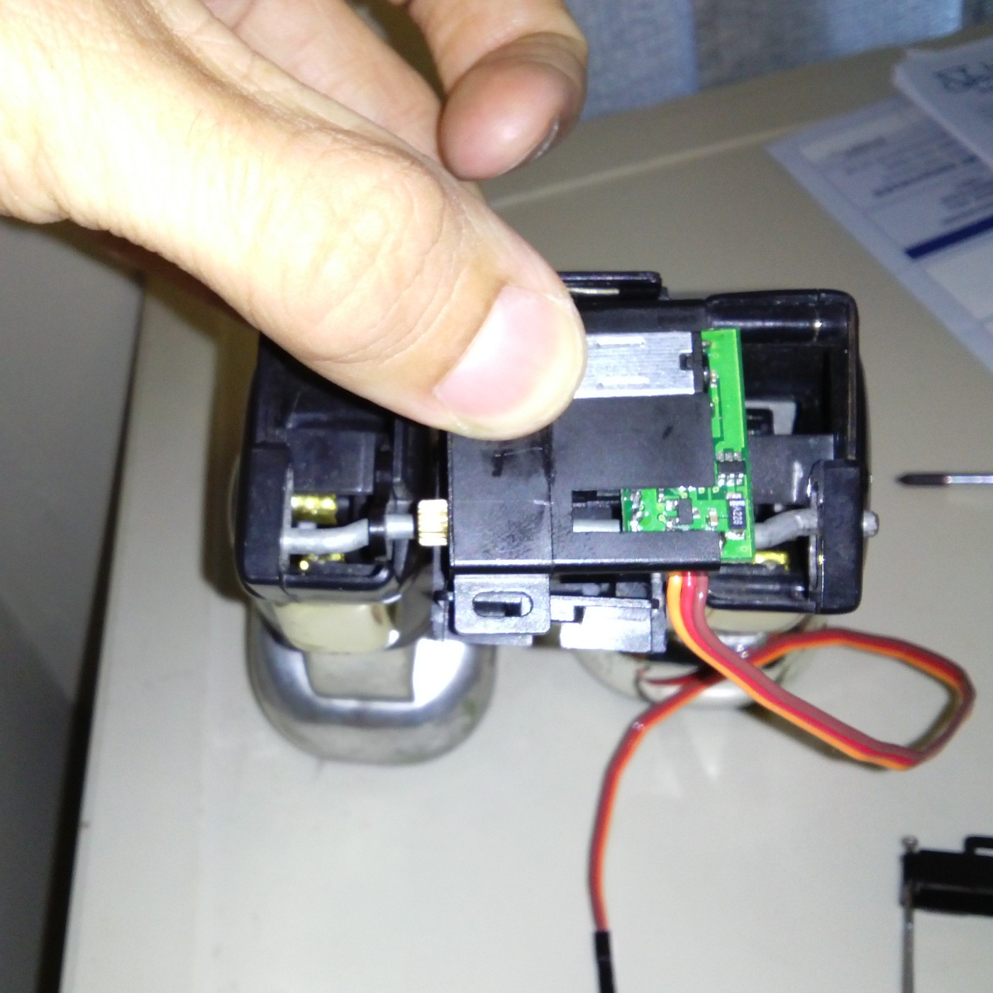
You can see that the servo was almost narrow enough to fit between the legs, but more importantly, the output shaft was exactly where it needed to be. I unsoldered the circuit board from the back of the motor and moved it out of the way of the shaft, this made the servo narrow enough to fit.
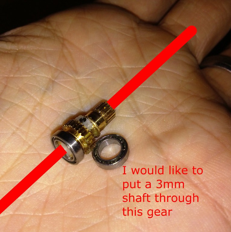
A friend was good enough to put a hole through the length of this little gear with his milling machine (although an accurate drill-press and some careful clamping would have sufficed I imagine). There isn't much room for error, since the gear is 4mm at its narrowest diameter and the shaft is 3mm.
This is the picture I sent him to describe what I needed:
Here the servo is mostly reassembled, with a 3mm shaft passed through the gear (I salvaged the shaft from a busted old business card scanner).
The next step was to recreate the dogleg shaft that drives the legs. Since I obviously can't pass the original bent shaft through the gear I attempted to make a new shaft, in pieces that would bolt together.
This drawing shows the idea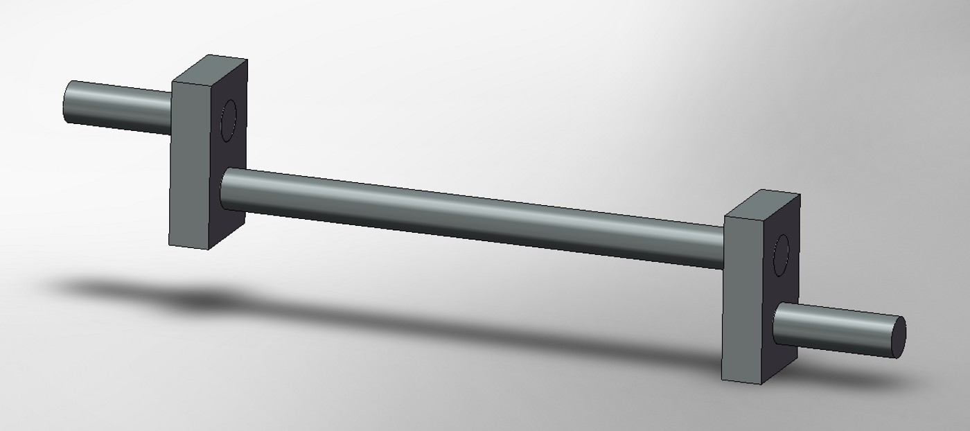
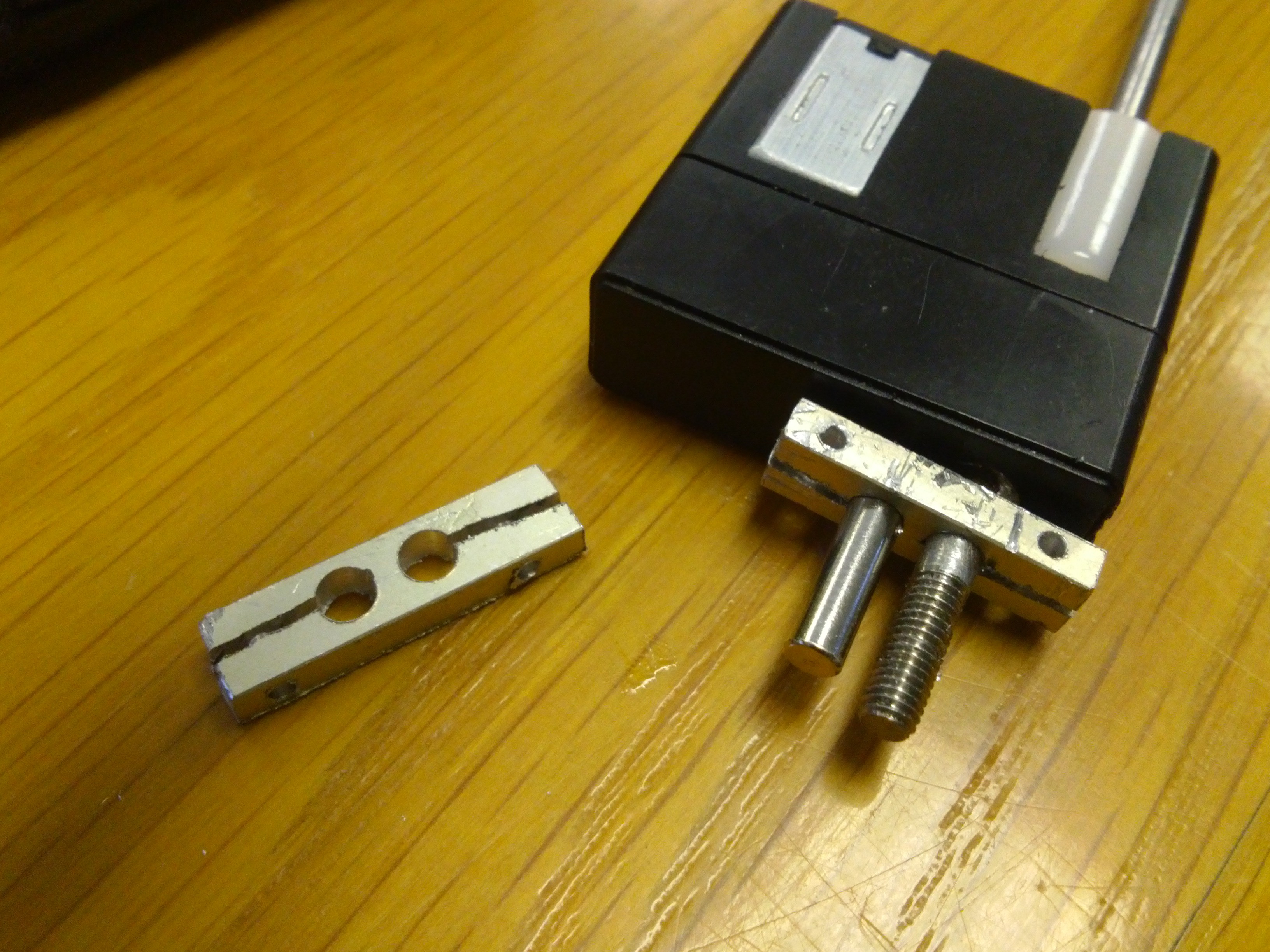
I set upon some scrap aluminium with the Dremel, drill-press and hacksaw to make some brackets. Here you can see one of the earlier attempts. The brackets actually worked out quite well, considering their small size and my tool selection, but when I tried to reassemble the whole thing, the tolerances just weren't tight enough and the legs kept jamming.
 After staring at it all for a while I went a new direction. If I could cut the original shaft in half, put it through the servo gear and then reassemble it, all would be well. I would drill two holes in the shaft, then put a sleeve with matching holes over it and screw it all together. Unfortunately the drill slipped off the shaft, even though I had filed a flat spot to try and prevent this, and kind of cut it in half.
Next I took an M3 brass hex standoff and drilled the thread out with a 3mm bit. It was easy to drill a 2mm hole though the center of one of its sides after making a little dent with a punch. With a 2mm screw through that hole I could slide the two half shafts in and the screw kept them orientated correctly, since their ends were crescent shaped (from when i cut them in half with the drill by mistake).
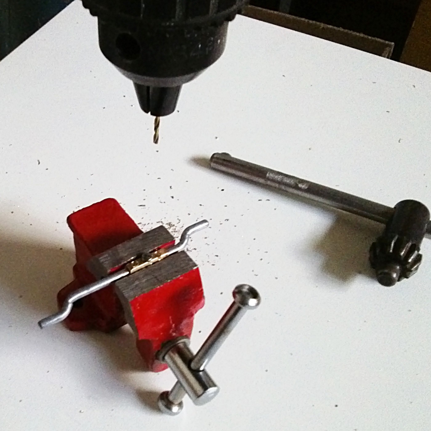
The flat surface of the standoff meant that I could now (very slowly) drill a 2mm hole through the standoff and the shaft, without the drill skedaddling all over the place, and then bolt the two halves together.
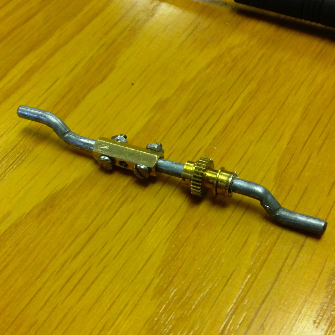
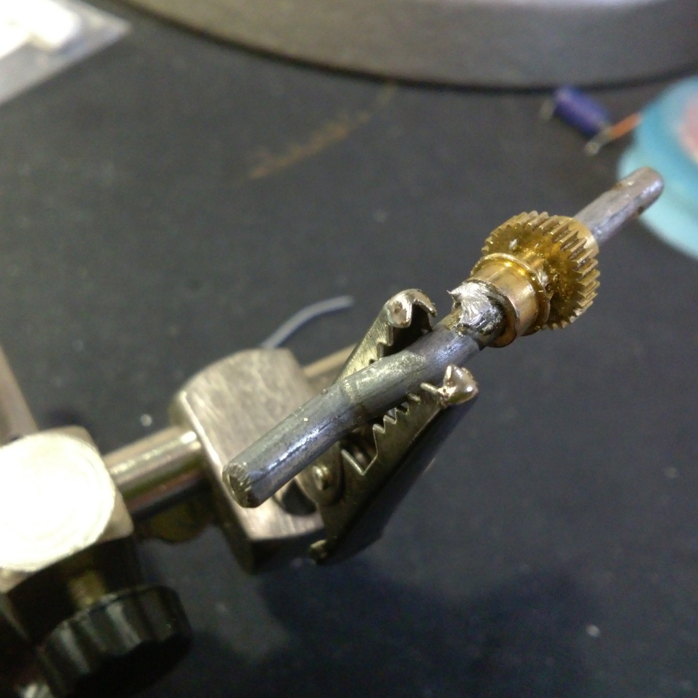
I then used a regular soldering iron (actually, two at once, to get enough heat) to solder the gear to the shaft and prevent it slipping.
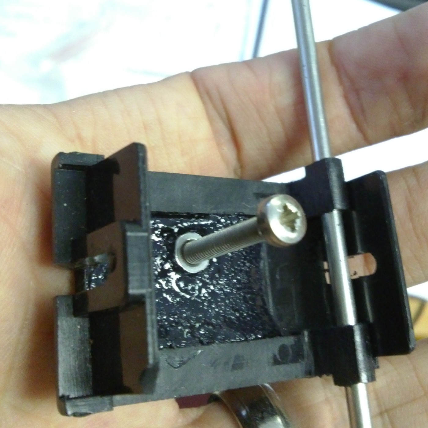
 Once this was all sorted I still had to mount the servo into the plastic pelvis bit. If possible I am trying to prevent the robot looking at all different from the outside, so I couldn't just put a screw right threw it. Instead I drilled through the servo and slightly into the pelvis plastic (to leave an indent that I could use for alignment) and the used a bit of Smooth
Cast Onyx resin that I had lying about to fasten a nut in place.
Once this was all sorted I still had to mount the servo into the plastic pelvis bit. If possible I am trying to prevent the robot looking at all different from the outside, so I couldn't just put a screw right threw it. Instead I drilled through the servo and slightly into the pelvis plastic (to leave an indent that I could use for alignment) and the used a bit of Smooth
Cast Onyx resin that I had lying about to fasten a nut in place.
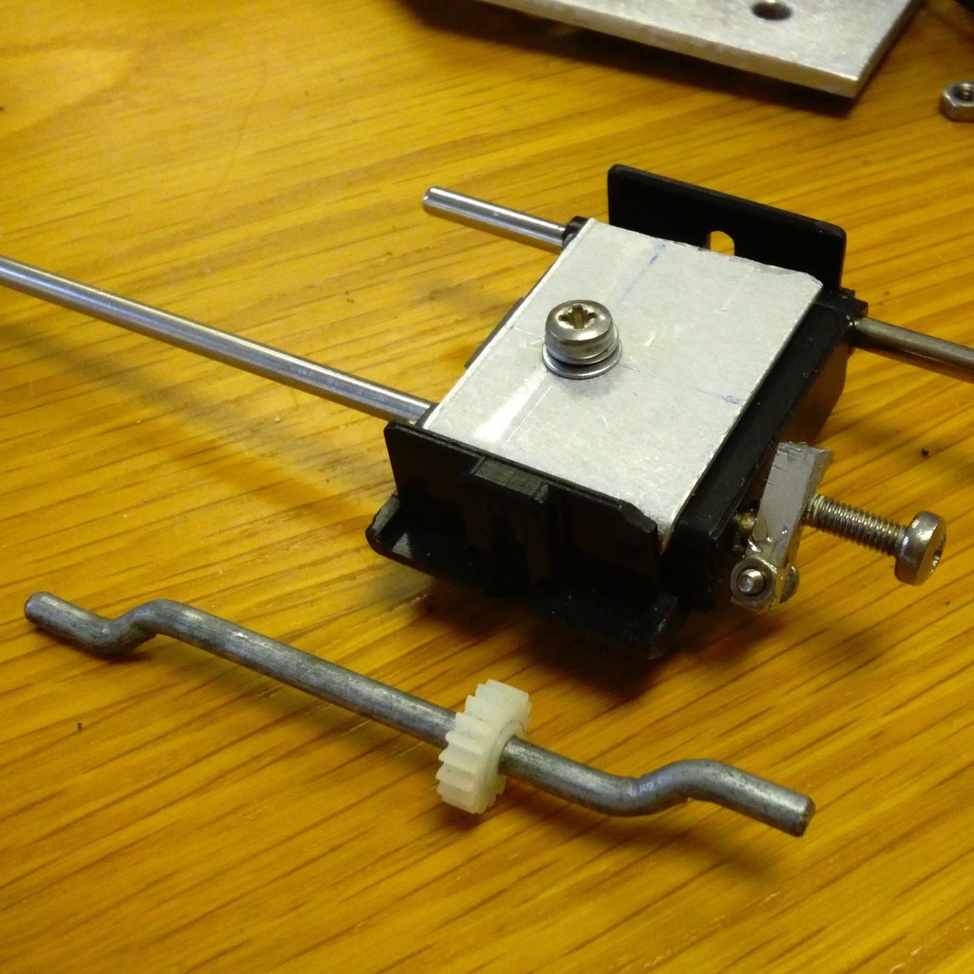
 A bit of bent aluminium with a hole in the right place keeps everything together (this is with the failed drive shaft, but you get the idea)
Now the whole caboodle could be reassembled, the servo circuitry re-installed, and the legs taken for a test drive.
Here is the part you have all been waiting for, a 16 second video:
I am actually extremely pleased with how it worked out in the end. The whole thing is more compact that I could have hoped for, which is probably a good thing, because as you will soon see, I am running out of space for batteries, micros, speakers, torso servos and so forth.
Discussions
Become a Hackaday.io Member
Create an account to leave a comment. Already have an account? Log In.