 Ossum
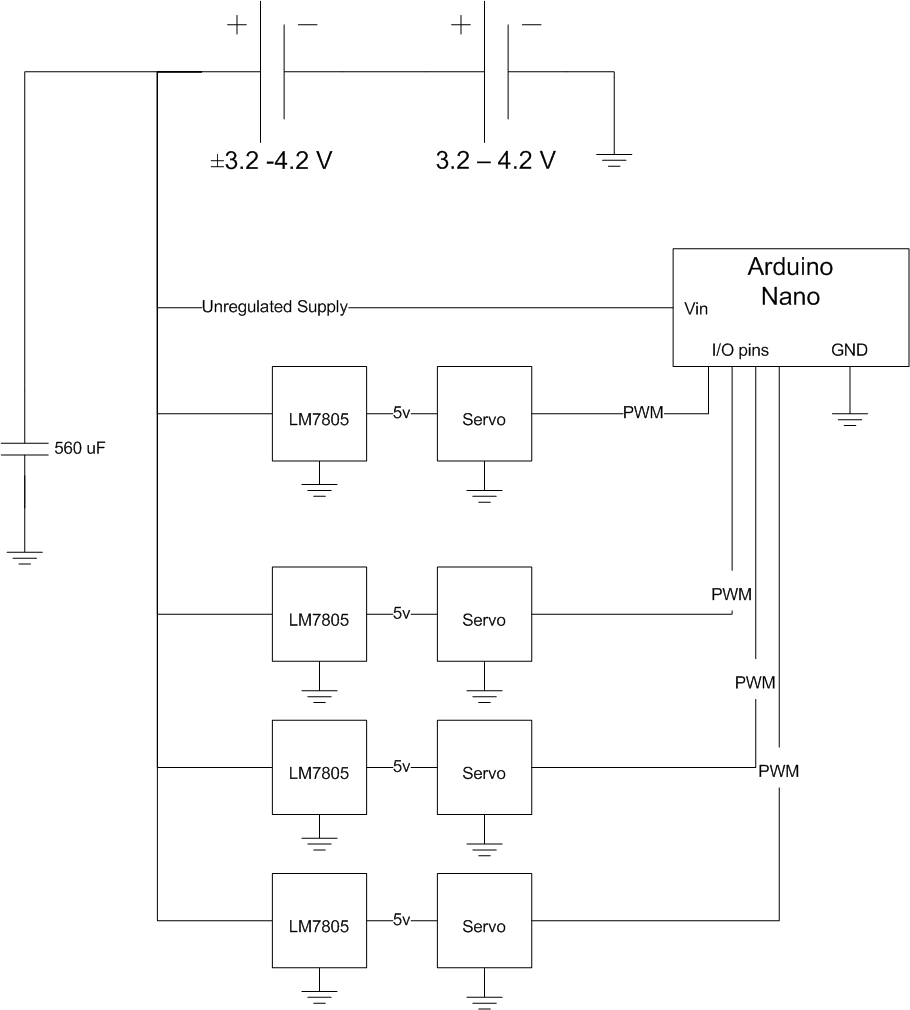
OssumMost of the components in the robot require 5V (some can take more than 5V, but the servos could not tolerate the 8.4V that the batteries would supply at maximum charge). The arduino has a regulator onboard, but it is not sufficient to supply regulated power to everything, so I need to find another way of supplying 5V to the components that needed it.
The metal gear servos seemed to be drawing close to an Amp when under load. I don't have any compact 5V switching regulators handy, so linear regulators are going to be the order of the day. They were easy to scavenge from old telecoms equipment.
A LM7805 regulator is only rated around 1 Amp in the TO-220 package, depending on heat sinking, so we decided to go with one per servo. This also left extra capacity, especially for the regulators powering the 9g arm servos, to power anything else that wanted 5V.
I ended up with a circuit as drawn below. The capacitor was definitely needed, the regulator's output was not stable under sudden loads without it. The value was pretty much just what i had lying on my desk though.
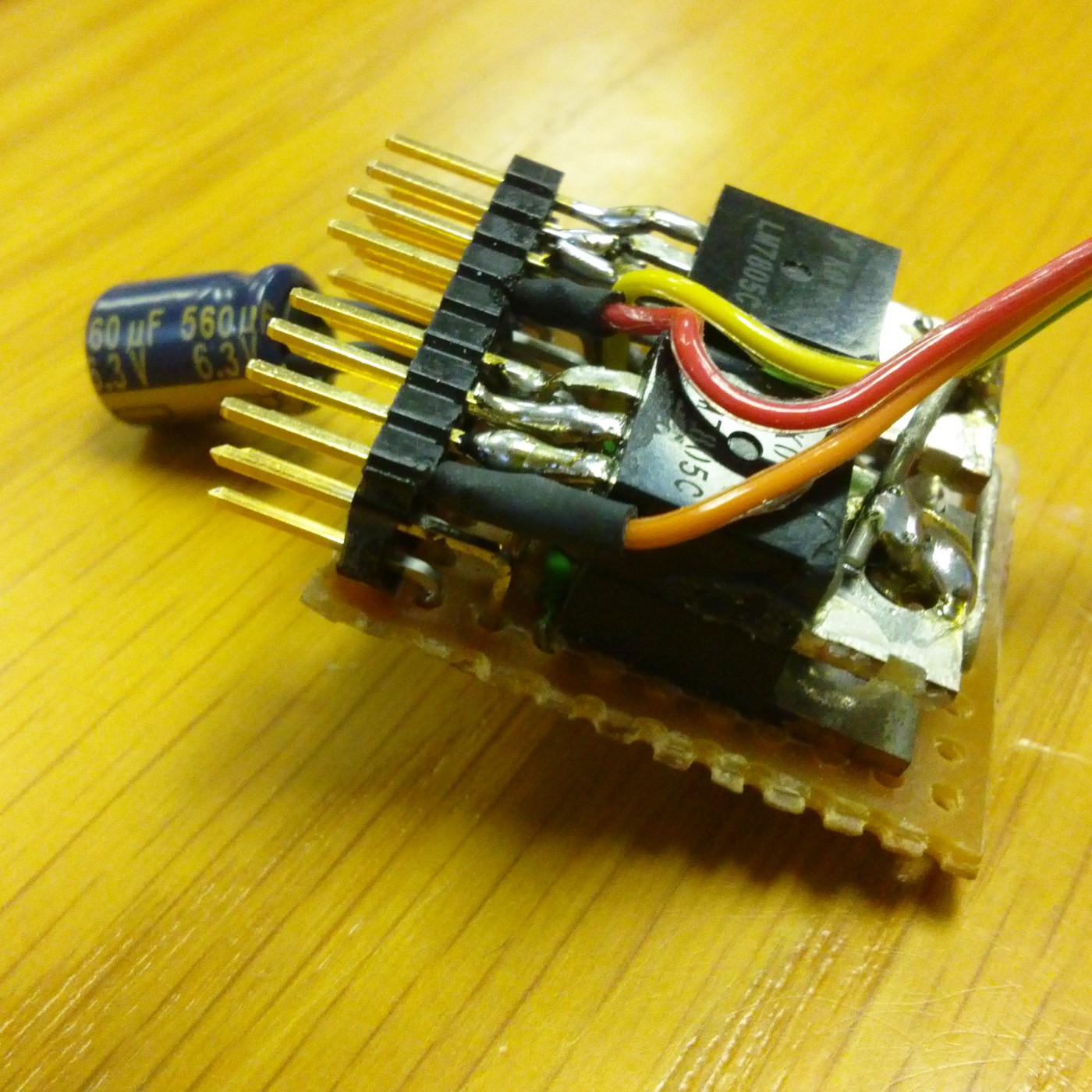
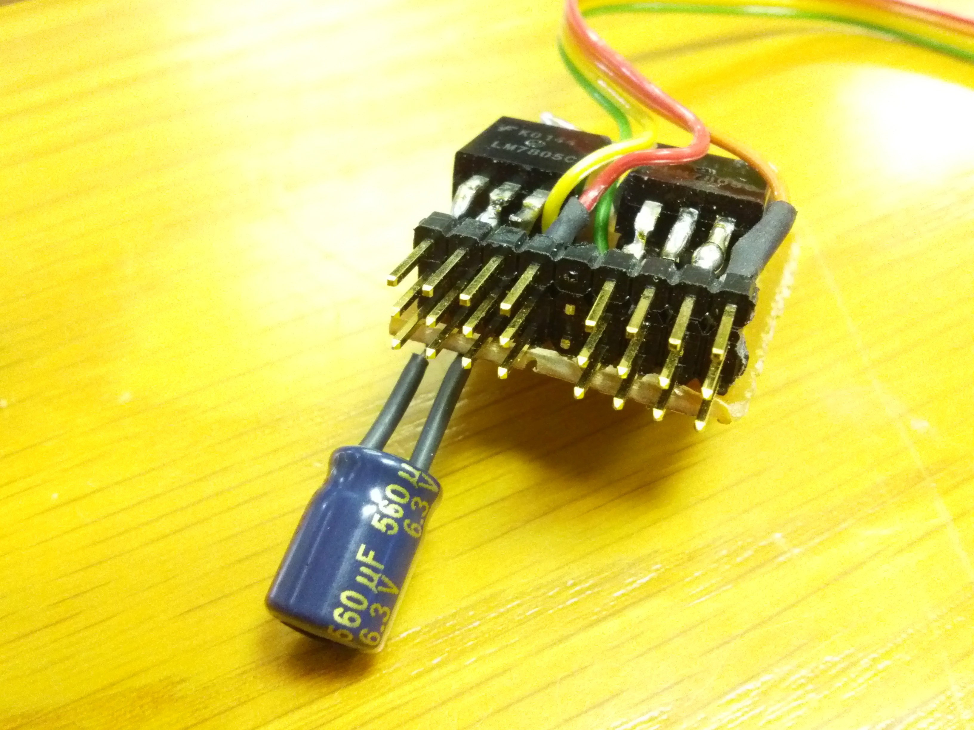
 My first attempt was too bulky to fit into the torso, so I remade it into what you see below. The bottom two rows are in series, which gives me extra pins to take off regulated or unregulated supply as needed.
The ribbon cable brings in the IO pins from the Arduino, meaning that one can just plug in a standard 3-pin servo connector. Obviously this setup is not ideal for heat sinking, but space is at a premium, they are all running under capacity anyway, so it seems to be fine so far.
Discussions
Become a Hackaday.io Member
Create an account to leave a comment. Already have an account? Log In.