 peter jansen
Here's a mega update, with a great deal of both progress and pictures!
With the successful first scan of the peach several updates ago, my focus has been on taking the design from a prototype towards a finished, complete unit. The main issues have been:
- In it for the long haul: While the first images have been captured, real performance will only come when the system has been properly calibrated and characterized. Given the long integration times associated with the very low intensity Barium-133 radioisotope, this essentially means the system has to run for between hours to days, standalone, collecting (first) calibration data, then image data once the system is calibrated. If it takes a day to acquire a solid noise profile while the system warms up, and a week to complete a scan, that's how long it takes. Imaging by counting single photons is for the patient.
- Power supplies: The first scan required several bench supplies, but ideally the final system should be stand-alone, and function on a single supply (like a brick). Noise is a tremendous issue here for the detector array -- and having a single low-profile supply that supplies the Pi and stepper motors has to deal with both high and low frequency noise -- and a fair amount of current.
- Raspberry Pi: The system needs to run standalone off the Pi, and ideally be accessible over WiFi.

Integrated Power Supply
I'd previously decided that for simplicity I'd use a separate supply for each major system (Pi, Motors, USB Hub, Detectors), both to help isolate the noise, and given that each requires a fair amount of current. While the switching supplies I'd evaluated earlier were efficient, they were very noisy -- and extreme analog filtering suitable for subatomic particle detection not being my forte, I decided to use linear supplies. It turns out the 7805S linear regular variant can supply up to 2A (with plenty of heat sinking), making it suitable for the PI, steppers, and more than enough for the hub and steppers. After breadboarding the design to verify its noise characteristics, I designed the board above to fit under the unit, in a single quarter of a pie shape.

A mystery ensued -- for some reason the design worked on the breadboard, but when using the proper board above, the detector channels showed a great deal of noise -- far more than to be usable. I disconnected the detectors from the purple supply, and connected them back to the breadboarded version, and the noise level was the expected low level. This was unusual, but such incredibly low noise supplies are new territory for me, so I'd assumed that some noise was leaking through the air, ground plane, heat sink, or some other place. I resolved that the detector supply may just have to be on it's own board, and put the above board together.
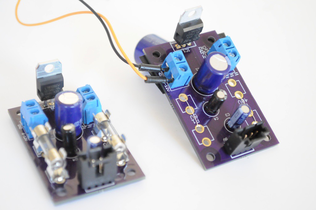
Except, the mystery continued -- after waiting two weeks for that board to arrive, I assembled it, and the noise was /still/ there. I wasn't sure what could be the cause, so I started building another board (right) piece-by-piece. Did the board need a larger input filter capacitor? Were the fuse holders acting as tiny antennas and picking up noise from the air? It ended up that the 7805S 2A variant has different noise characteristics than the 7805CV 1A variant I had populated the breadboard with while waiting for the 2A versions to arrive from Digikey, and this was the source of the issue. Swapping out the S with the CV for the detector supply on the quarter-pi-shaped board caused the noise level to return to normal. Great!
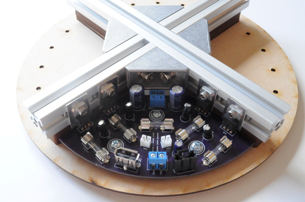
Linear supplies require a large heat sink to dissipate all the heat they generate. Mechanically, I also needed a support bracket both to rigidly support the weight of the device while also providing an anchor point to bolt the outer cylindrical housing (an 8 inch diameter PVC pipe). I ended up cutting some 20mm aluminum extrusion into the above pattern, which allows the regulators to bolt directly into the t-slots, and supplies a very large thermal mass to dissipate all the heat of running the system (and, the Pi) continuously for days on end.
Mounts for the Control Systems
I confess that figuring out a place to mount everything proved more of a challenge than I had originally anticipated. This was compounded by having to add a USB hub, given that the few USB ports on the Pi did not appear to be able to reliably deliver power to USB devices plugged directly into the board. This was especially noticeable with the wireless connection dropping out periodicially, likely through the Wifi dongle browning out.
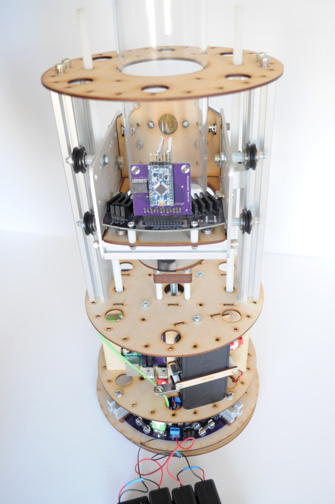
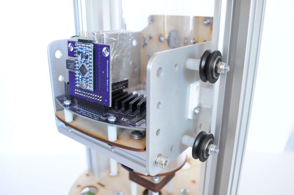
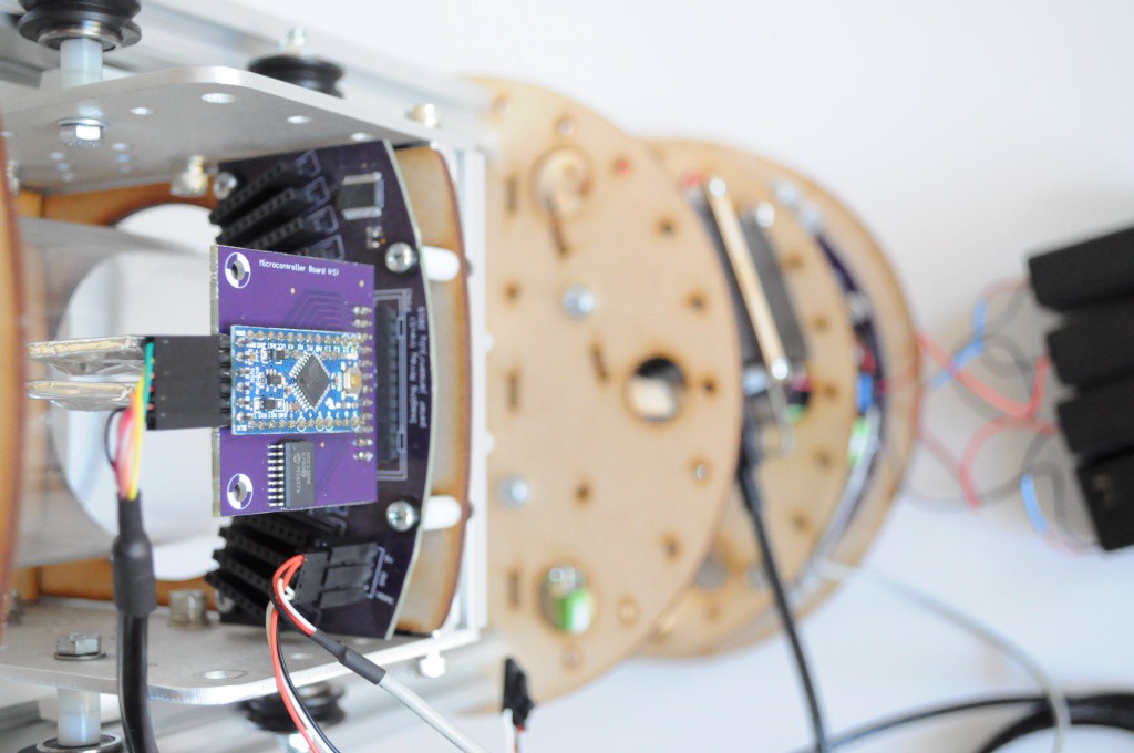
After trying several different configurations, I settled on the one above -- The Pi and hub on one side, with the Arduino and motor controller on the other. The power supply fits below (1/4 of the pie), with two compartments for the batteries required for the photodiode bias supply (2/4 of the pie). The remaining section of the pi is reserved for a backplate, to mount the power switch, DC power connector, and other connectors.
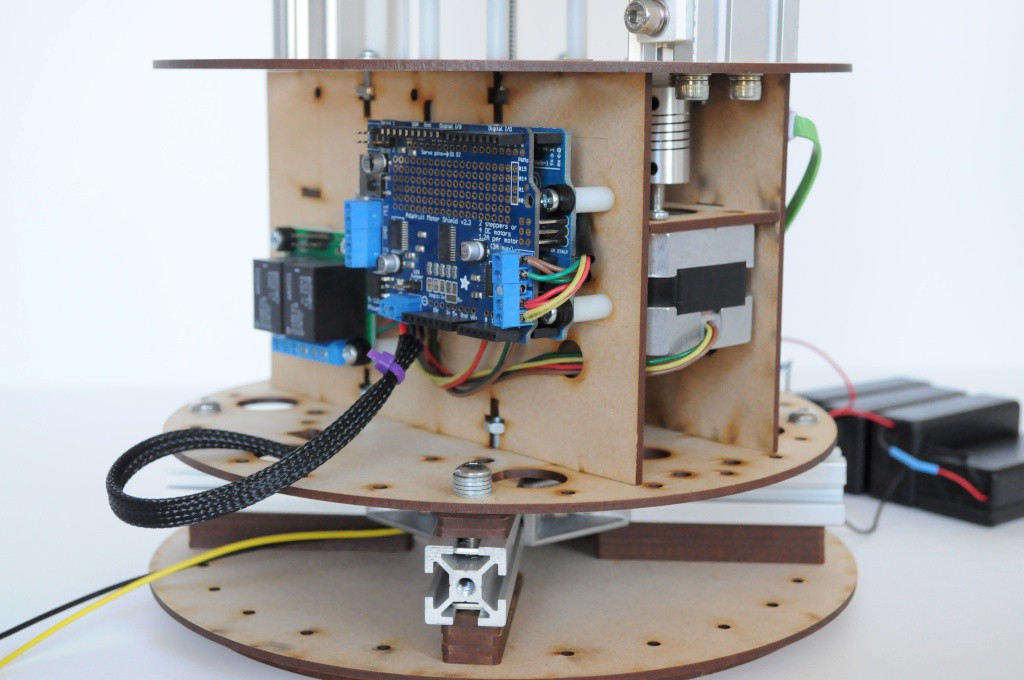
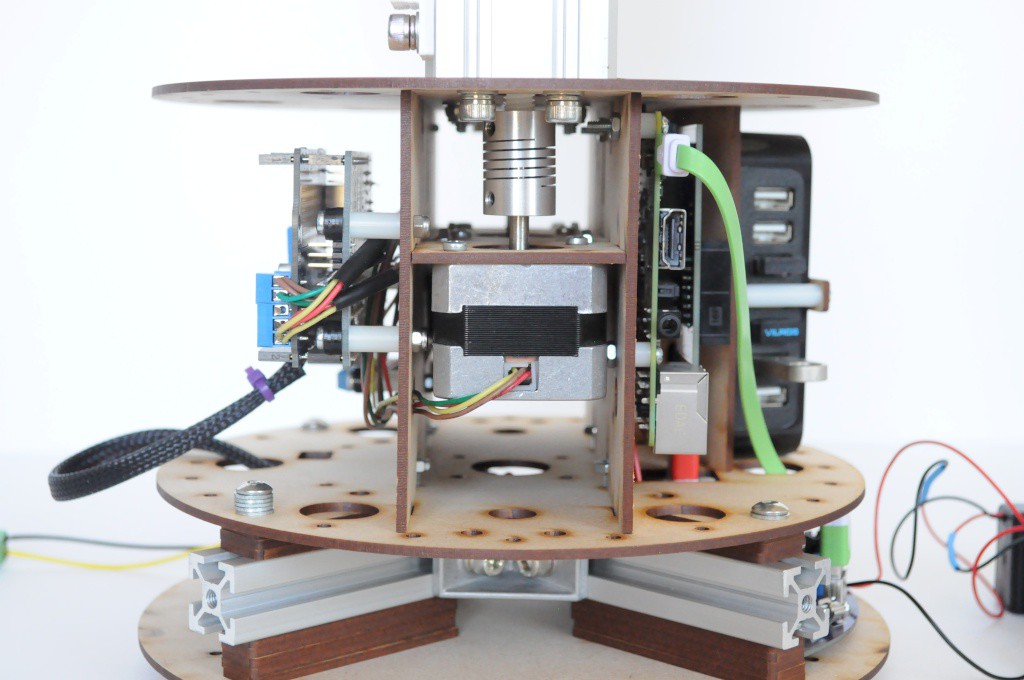
The motor control side is shown above. In keeping with trying to have everything either off-the-shelf, or very easily assembled if an off-the-shelf solution isn't possible, here I've used an Arduino Uno and Motor Controller Shield, that should be easy for most folks to source.
I've also included a Pololu relay shield to enable or disable the 40V photodiode bias supply, in the form of the four 9V batteries, so that they don't drain unnecessarily. That being said, the draw seems to be exceptionally minimal, and I've used the same set of four batteries for the entire duration of the project without any issue, but it's still better to be safe and err on the side of having to replace batteries once or twice a year rather than every week or two.
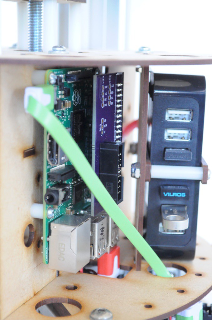
The Raspberry Pi and USB hub mount to the other side of the cylindrical scanner. The hub mount is designed with a little flexibility, and many low profile hubs should fit, but I've designed this holder to specifically fit an easy-to-find USB hub from Best Buy. This hub also just happens to have very reasonable noise characteristics for the devices that it powers.
The extra hat on top of the Raspberry Pi connects the GPIO connector to a smaller connector for connecting to a small control panel and display (shown below).
Another angle on the power supply board. There's still some mechanical work to be done to ensure that the apertures in the structure are appropriately placed to allow cables to move through easily. The green and red USB cables are standard low-profile cables available in bulk on Amazon.
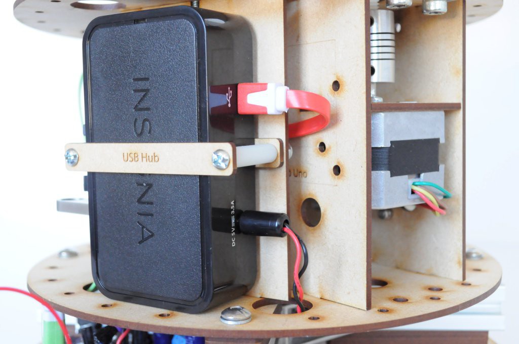
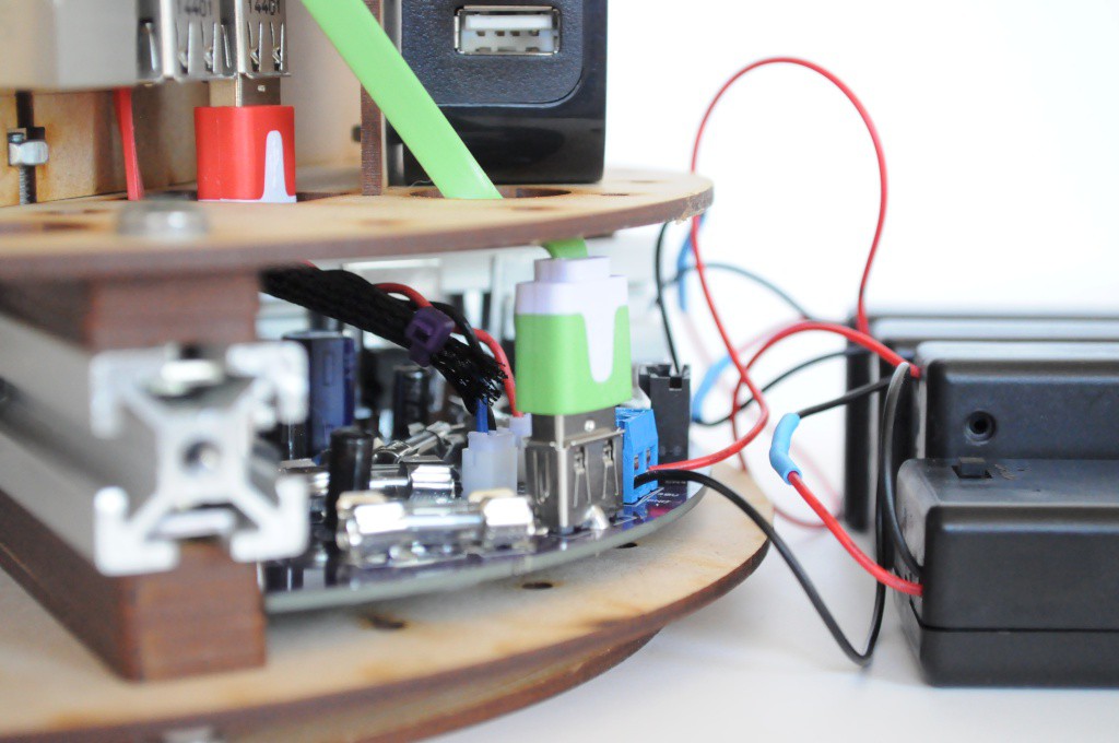
Another angle, here the back of the USB hub. The USB connection connects to the Raspberry Pi, and the DC barrel connector connects to one of the channels of the power supply board below.

And, the four 9V supplies that function as the extremely clean V_bias photodiode bias supply. The draw on these batteries is very low, so I suspect that they'll likely be good for many months without requiring being changed. Ideally these will eventually be replaced with an ultra-low-noise supply, but this is a low priority.
As it turns out, I also had issues with /this/ supply, in spite of it being only four batteries in holders! Each holder has a power switch, and two of the power switches were reversed!
And, a large milestone -- the entire device can now be supplied from a single, inexpensive, and easily available (switching) brick supply instead of a series of expensive bench supplies. It took far more work than I'd expected, but it's wonderful to be in a working state.
Control Panel / Navigation Pad
The top of the scanner is about 8 inches in diameter. I've decided that, in addition to accessing and using the device over Wifi, it would also be useful to have a status display on the device itself showing the progress of the current scan, pictures of the latest slice, common settings, and so forth. Given the simplicity of the device, the user could even setup and initiate a scan from the control panel.

Keeping with the mantra of making everything either off-the-shelf or easily assembled, I've used an Adafruit OLED breakout and combined it with a wonderful navigation button pad I found after browsing through nearly every directional pad on Digikey.
Though not shown here, I've ported the OLED Framebuffer driver from the Arducorder (itself based on the Adafruit Arduino driver for this screen) to the Raspberry Pi. The display appears to work well, and I'm hoping that like the Hamamatsu Microspectrometer reference schematic and driver for the Arducorder, that this modular screen and navigation pad may be easily reused by other folks in their projects.
One issue that's come up is that this breakout board for the OLED screen appears to emit quite a bit of noise, and raises the baseline (noisy) number of counts on the detector array by a factor of three. I'll likely have to come up with a way of isolating this board, or placing some extra filtering on the detector array and microcontroller boards to mitigate this issue.
End Stops
One of the small but critical aspects still remaining is that both the linear (Z) axis (above) and rotational axis for the table require end stops/limit switches. This is both for homing each axis before a scan, as well as preventing accidental over-travel on the Z axis.
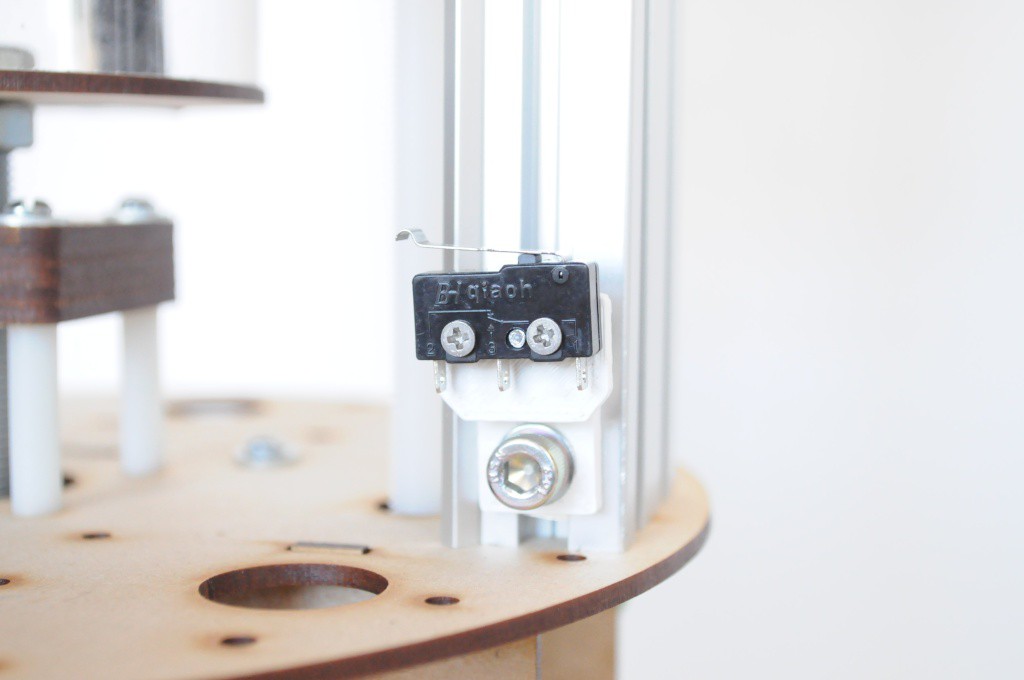
Figuring out an ideal place to mount the limit switches required some thought. I'd initially thought of mounting them on the top/bottom plates, but this would require a fair amount of travel. I'd also considered mounting them directly on the carriage, but then they'd be in motion, and require a moving cable, which increases complexity. I finally settled on this much simpler solution -- a small 3D printed bracket that mounts to the Makerslide linear rail.
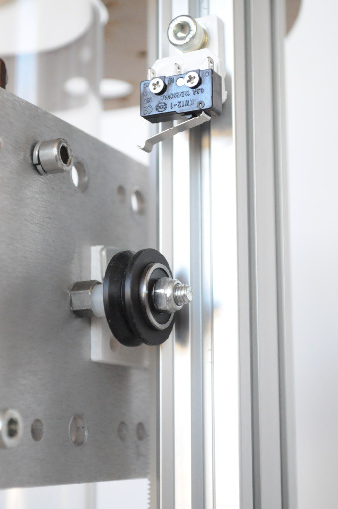
The business end of the limit switch fits beautifully inside the V-groove of the V-wheels on the carriage. Being mounted on the Makerslide also allows for very easy adjustment.
Cabling
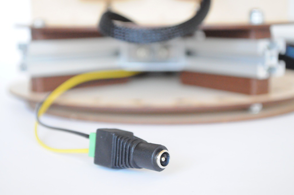
While the pictures above have omited a bit of the cabling for clarity, there are still one or two cabling issues left to resolve. These are largely centered around the moving carriage, and figuring out an ideal mounting pattern that allows the 6-8 inches of cable travel without fear of the cables becoming pinched during the motion.
The two cables on the carriage include the power cable for the detectors (plugged directly into the imaging array, above), and the FTDI USB->Serial cable that plugs directly into the Arduino Pro Mini on one end, and the USB hub on the other. This cable is rather -large, and not terribly flexible, so I'd like to find a shorter and lower-profile solution.
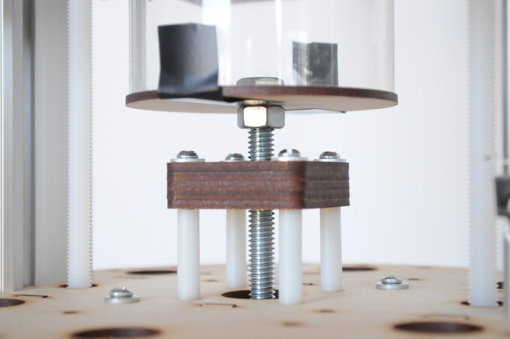
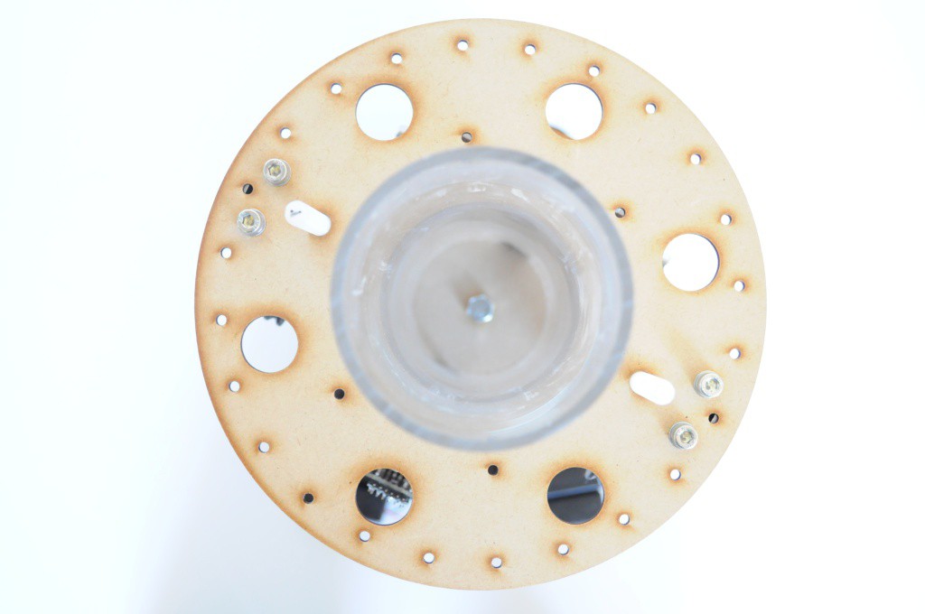
Table and Sample Container
The final major mechanical bit that needs designing is the sample container/rotational table mechanism. The placeholder that I quickly put together is above, which is simply a 3 inch diameter circle attached to the end of a long 8mm bolt coupled to the center stepper motor. A captive bearing in the center block supported by the nylon standoffs helps keep everything relatively aligned. While this supports whatever I place ontop of it, it's been more of a rough sketch rather than a final working unit.
Ultimately this system requires:
- A keyed table and sample container, that interlock when connected together.
- A limit switch, or other way of determining a 0 degree rotational reference for the table.
- A block of lead, or another heavy absorber, blocking the majority of emissions from the source. This will allow the carriage to park here at the bottom when not actively used (and during calibration runs), blocking all emissions from the source.
I've been designing a next-iteration of a laser cut the keyed/interlocking table and sample container, but an elegant way of mounting the homing switch for the rotational axis and the blocker for the source hasn't presented itself yet. Hopefully that will be the next major addition!
Thanks for reading! And stay tuned!
Discussions
Become a Hackaday.io Member
Create an account to leave a comment. Already have an account? Log In.
Wonderful progress, and it's nice to see PCB in non-rectangular shapes; particularly when the form enhances the function (as in the power supply, above).
I recently saw a nice piece about using a switchmode supply module to feed into a linear regulator in order to maximise the efficiency, and that might be useful in the future.
You might consider a "lazy susan" style rotating table, and you can put optical sensors / photointerrupters on the perimeter such that you can interpret a quadrature or absolute code without limiting your rotation. An off-the-shelf rotary encoder might be more called for.
Also consider not mounting the stepper motor directly to the shaft, but coupling it via a timing belt; you're likely to be able to maintain vertical alignment better and remove some of the "wobble". There are multiple ways of doing this whilst minimising the pull on the shaft; have a look at model helicopters main shaft drives for some examples.
If the z-travel endstops are annoying you, you could try one of the induction sensors that are cropping up on 3d printers and use an aluminium platform. It would also allow you to calibrate for any offset of the bed on rotation (home-rotate-home-rotate...^n & then transform
Continue the good work!
Are you sure? yes | no
Great write up mate!
Are you sure? yes | no