 peter jansen
I've been thinking about tomographic imaging a lot lately in between nursing sore fingers from learning how to hand-wind electromagnetic coils for my attempt at a small prepolarized coded-field MRI, and I thought I'd take a moment to share some progress.

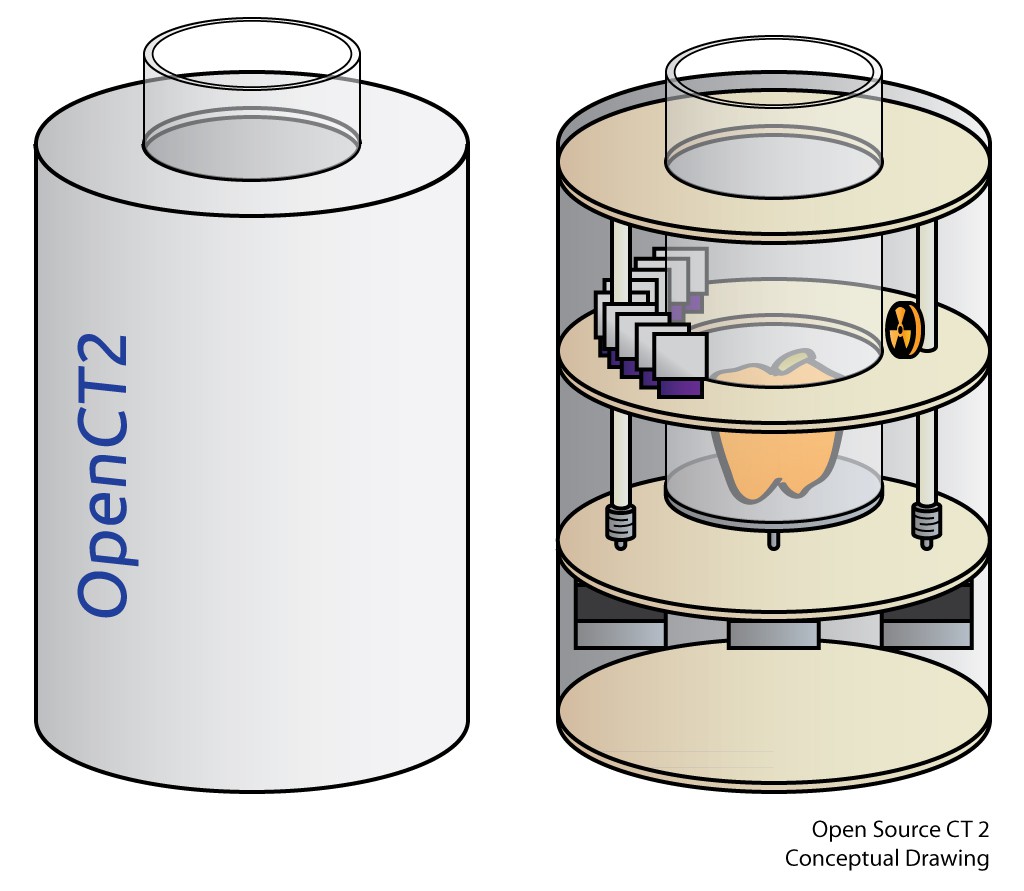
The open source computed tomography (CT) scanner that I put together last year was a lot of fun to design, having many atypical design problems in it, from the mechanical design of the rotary gantry to pairing an appropriate radioisotope source with a modified extra-sensitive radiation sensor. Something about it being essentially a radioactive desktop Stargate that lets you see inside of things also seems to get people very excited, and so I've received an eclectic bunch of e-mails asking about the scanner from folks as diverse as radiology professors and biomedical folks to makers to those hoping I'd open up Dr. Jansen's back-alley CT scans to have a look at some strange bump they have (please go see your doctor!). But I feel that for all the excitement, to quote Feynman, the current open CT design feels a bit like a dog that walks on two legs — it's not that it does it well, it's that it does it at all. It's essentially a working model of the first generation of CT scanners, and so it takes a very long time to get even a single slice of an image. I've been wondering what it would take to move it from a proof of concept into something that does the job well, or at least substantially better.
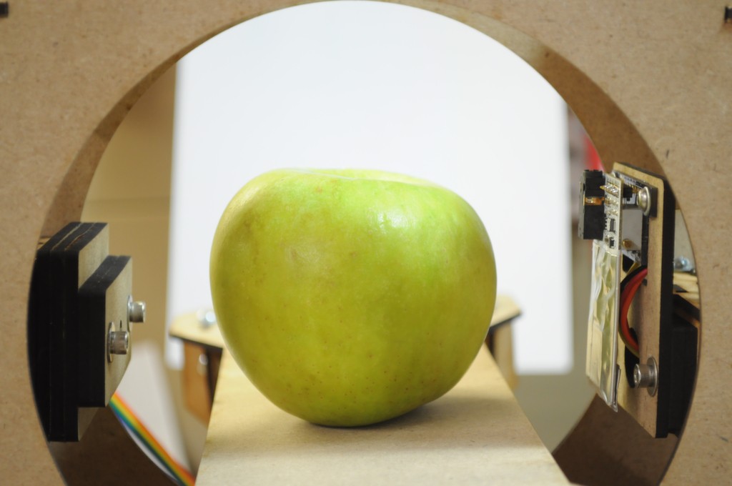
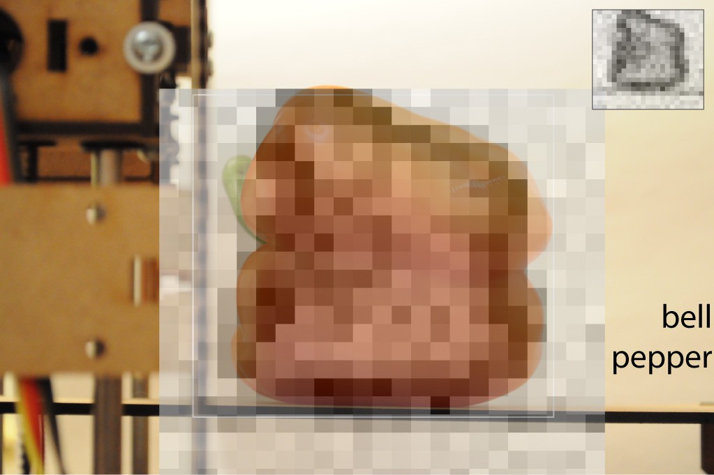
The previous design makes use of a 10uCi Barium-133 radioisotope check source, which is the strongest radioisotope source that's available without a licence. Barium-133 has strong x-ray peaks around 31kEv and 81kEv, which are low enough energy that organic water-containing materials (like apples and bell peppers) are reasonably contrastive for imaging. The silicon PIN photodiode detector in the Radiation Watch Type 5 high energy particle detector that I used is also most efficient at low (~10kEv) energies, meaning that we would need less exposure time to generate an image with sufficient signal to make things out, although there are technical challenges in detecting these lower energy photons. Imaging under these circumstances is essentially a constant battle for detecting signal over the noise, and one way to generally increase SNR is to increase the measurement time — although of course this increases how long it takes to create an image. In the extreme case when you're so signal starved, it ends up taking all night just to capture a single slice of a bell pepper.
Another alternative that's been suggested is to increase the intensity of the x-ray source. For a variety of safety reasons this isn't something that I'm willing to explore. I've heard of folks experimenting with surplus x-ray tubes and equipment, and I believe that your health is just too precious to risk for such endeavors. Pragmatically, as an open source project, using readily available radioisotope check sources is also much more repeatable than found radiography parts.
And so we're left with a few alternatives:
- Decrease the scanning volume: The current design has a source-detector distance of about 12cm. Following the inverse square law, each halving of this distance should increase the number of counts at the detector by a factor of 4.
- Detect in parallel: Starting with second-generation CT scanners, parallel arrays of detectors were used to dramatically decrease scan time. This should give linear speed gains — e.g. N detectors should reduce the scan time by a factor of N.
- Increase sensitivity: Detecting the signal from single photons requires a genuinely incredible amount of amplification, and this process is noisy. While previously recalibrating the Type 5 detection threshold to just above the noise floor yielded many more counts, it appears as though much of the signal is still buried below the noise floor of the detector.
It's likely that a solution will end up with some combination of each of these alternatives.
Parallel Detectors
Where the first generation of medical CT scanners contained only a single photodetector, I've read that each generation of CT scanner after has increased the number of detectors by about an order of magnitude over the generation before it — moving from ~30 detectors in a second generation system, to ~300 in third-generation fan-beam systems, to ~2000 in modern static ring systems. Each of these improvements allowed scan times to reduce accordingly, starting from about half an hour with first generation systems, to about a minute, to now only a few seconds.
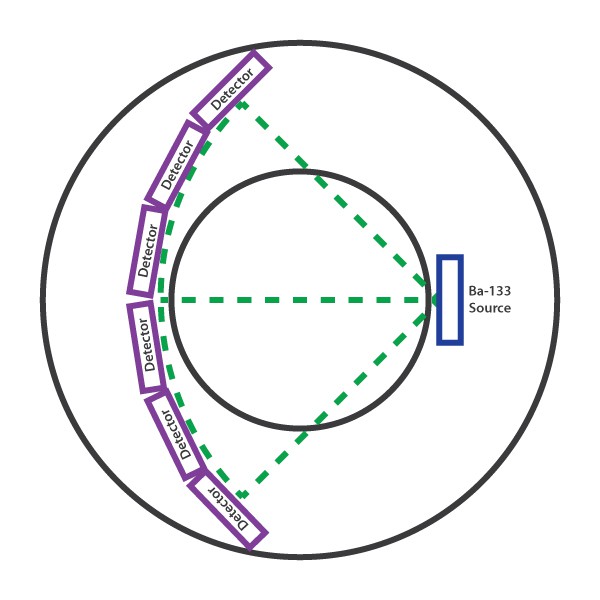
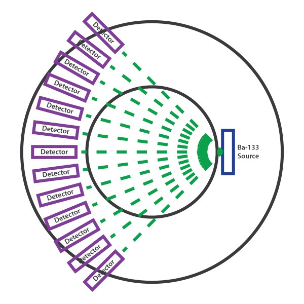
Above we can see how the current system might be parallelized with more Type 5 detectors, each arranged across an arc such that there is a constant distance between the source and each detector. The Type 5 is one of my favorite sensors of recent years, and I've had a lot of milage out of it, but unfortunately because it's about an inch across, it would be difficult to parallelize the desktop CT with more than about 6 detectors using this design. Additionally, the fantastic First Sensor X100-7 that the Type 5 uses has a 10mm x 10mm active area, which makes it great for collecting and detecting high energy particles, but a little large for the kind of spatial imaging that we're doing, so the images will be a little blurred. Having a smaller detection area will increase our spatial resolution, and decrease the detector size — so that (ideally) we'll be able to pack many more detectors in (as shown below), and decrease the scan time.
Designing an inexpensive parallel detector
High-energy particle detectors are extremely challenging to design and build, in large part because you're amplifying the signals from a single subatomic particle by many orders of magnitude in order to be barely detectable by a microcontroller. Because of this they're extremely sensitive to noise, layout, component selection, and generally must also be shielded from external interference. Given the design challenge I've been reading whatever I can find on the topic over the last few months, and meditating on layout guidelines to reach the zen-master level of low-noise layout required for such a task, or at least to get a prototype to a point that I can work from.
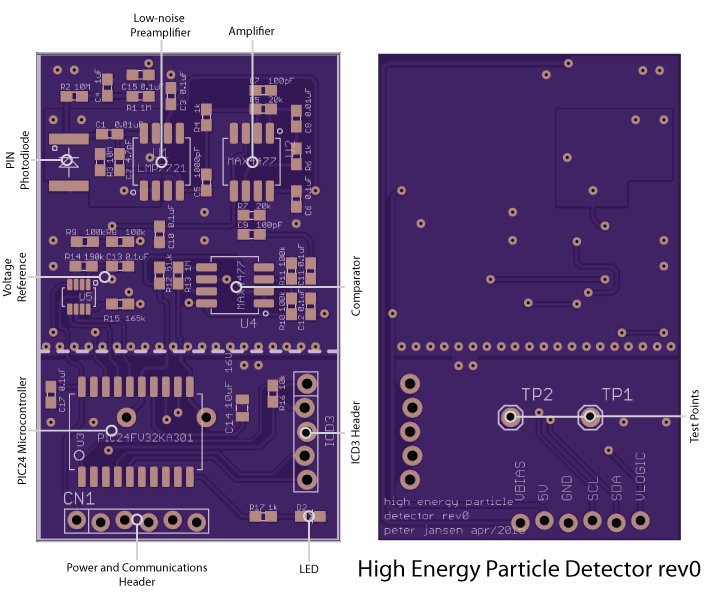
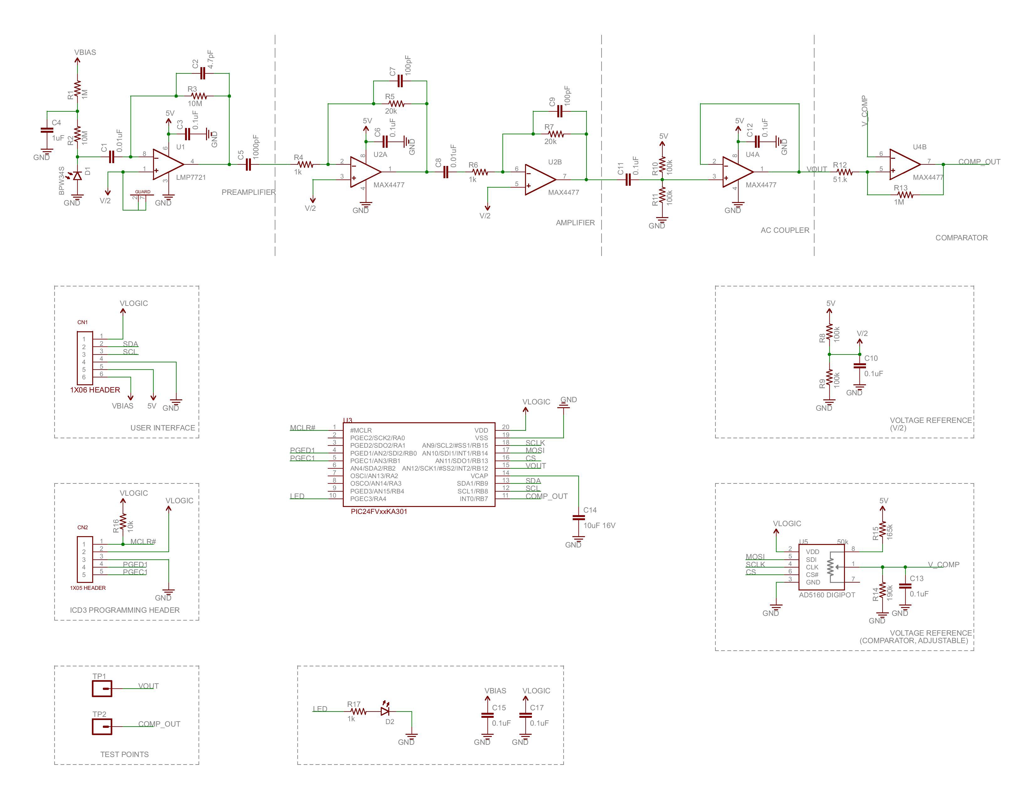
The design that I arrived at (schematic) is heavily based on the Maxim Appnote 2236: Gamma-Photon Radiation Detector, which uses a reverse-biased silicon PIN photodiode as the detector connected to an extremely sensitive first-stage amplifier, followed by a series of cascade amplifiers to increase the signal intensity. The photodiode is the popular BPW34, which has been used in a number of other radiation sensor projects. The active area of the BPW34 is only 7.5mm^2 (a little less than 3mm x 3mm), which is a little over 10 times smaller than the 100mm^2 of the X100-7, so this should increase the spatial resolution a good deal.
While many of the hobbyist designs for radiation sensors operate at effective noise thresholds of around 100keV or more, because here we have such a specialized application where most of the business photons are 31keV or 81keV, keeping the noise floor as low as possible to be able to detect these photons is critical. A number of academic project writeups for radiation detectors I've found suggested that the Texas Instruments LMP7721 would be an ideal choice for helping keep the first-stage amplifier as low-noise as possible, both because of its incredibly low noise characteristics (measured in femtoamps), and an uncommon footprint that includes guard pins to further reduce layout noise.
To make the boards modular and digitally addressable, I've added on a PIC24FV32KA301 microcontroller, which sports a 12-bit analog-to-digital converter (~1.2mV resolution @ 5V), and plenty of RAM to store a histogram of pulse widths to experiment with doing very crude spectroscopy as I've done with the Radiation Watch Type 5. Both the raw analog output of the photodiode amplifier as well as the digital output of a comparator serve as input to the PIC, and a digipot allows one to dynamically calibrate the comparator output based on the noise level at runtime. I've also included a small LED for debugging.
The PIC currently exposes an I2C interface (SDA/SCL) for external communication, though in retrospect while this makes communication easy, it would also require programming each detector with a unique I2C address — so future revisions might move to an SPI interface.
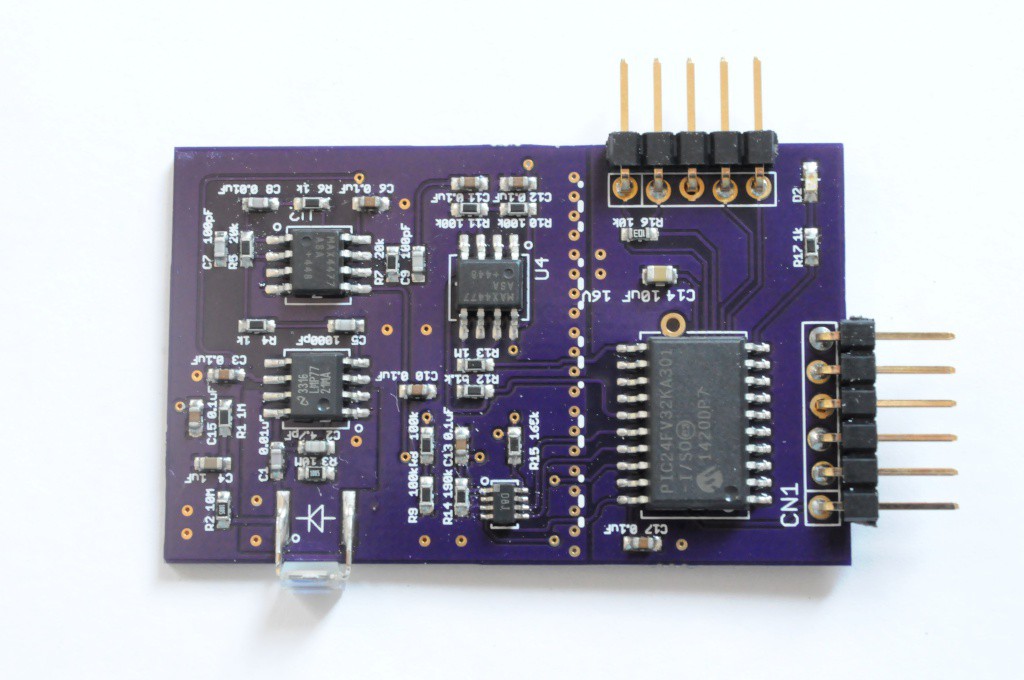
In terms of assembly, the memory of spending 4 days to assemble a set of fine-pitched Arducorder boards is very fresh with me, and so I've designed these to be very easily put together — a single-sided design with 0603 parts or larger on all the passives, and SOIC pitches on each of the ICs with the exception of the SOT-8 footprint for the digipot. So it's comparatively easy to build a bunch of these and pop them in the reflow oven, and with a low-quantity BOM of $20-$30 (about half of which is from the TI LMP7721), they're relatively inexpensive.
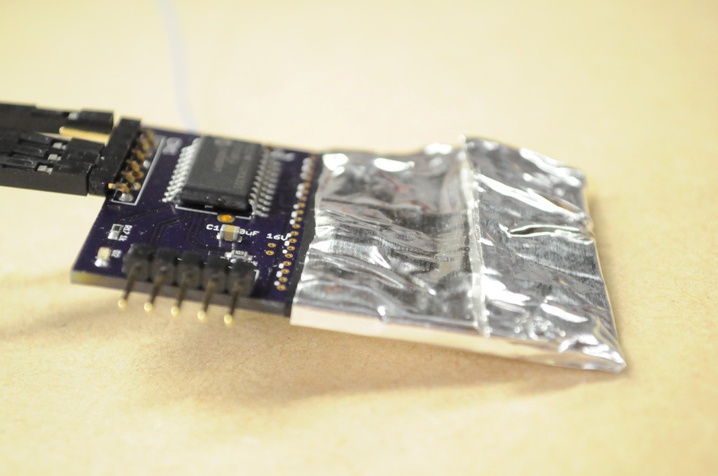
A series of guard vias on the ground plane divide the analog and digital sections. I've found that shielding the analog section and grounding the shield (like the Type 5) is absolutely essential for operation, much as the appnotes prescribe. I'm not sure what folks tend to use for the shielding tape, but I found that a wrap of electrical tape (to shield the photodiode from light and provide a non-conductive base) followed by a wrap of standard aluminum duct tape from the hardware store seems to work well as a first pass.
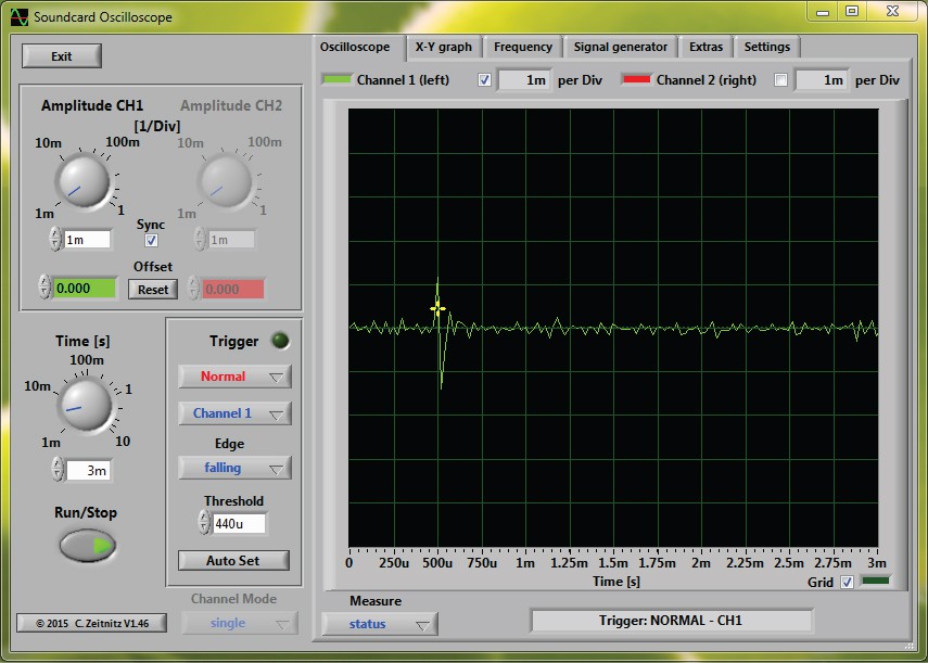
As an aside, for the low-field MRI project I've been looking for a USB oscilloscope or DAQ that would allow recording at at least 100KSps (ideally 1MSPS) at 12+bits of resolution for several seconds. This is a little unusual — usually scopes that are fast have very short sample memories. I'd seen an article about building a sound card oscilloscope in Make that would easily allow for such long recordings, as well as folks selling oscilloscope probes modified for sound card use, so I thought I'd give this a try before using a benchtop oscilloscope.
Above is a recording from the sound card oscilloscope with the Ba133 radioisotope source near the detector — and the detections were clearly above the noise floor. Wonderful news! The units on the axes aren't entirely clear here, and with such a slow sample rate we're right on the edge of being able to detect this signal, so on to a benchtop scope to better characterize things.
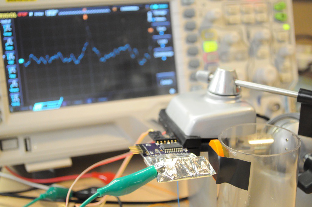
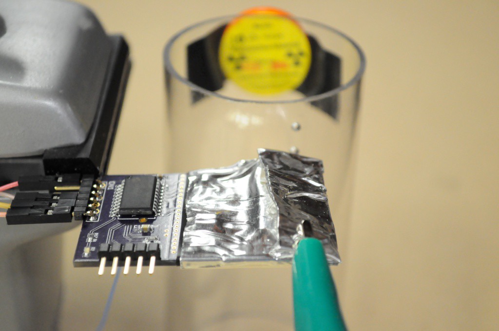
Here I've taped the 10uCi Ba-133 radioisotope source to the side of a 2 inch diameter acrylic cylinder. In this configuration I can easily rotate it to see the number of photons detected when the source is directly beside the detector, and compare this to when the source is 2 inches away, and going through a thin (1/16 inch) acrylic sample container.
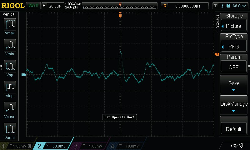
The noise floor generally appears to be around +/- 40mV, which is very decent for a first try, although it did appear to increase to nearly +/-60mV after being on for a few hours. I was also doing this at Xerocraft beside a metal shop, and the noise would periodically go a little crazy when a large piece of equipment (like the mill) was turned on, so I'm not entirely confident in the noise characterization — but it's a good start.

The firmware for the PIC isn't complete, so I was using the scope to trigger on the raw analog output instead of using the PIC (either with the analog output, or the digital comparator output). With the Ba133 source very near to the detector there were far too many detections to count, and with it 2 inches away going through the acrylic cylinder, I counted approximately 20-30 counts per minute. That's not incredible, but it's also workable, especially if the noise floor can be lowered, and we gain access to more signal.
To help ground this, the bell pepper image shown earlier was captured at about 22×22 pixel resolution, with about 60 seconds of integration time per pixel, for a total of about 9 hours of acquisition. Using a parallel array of about 20 of these BPW34 detectors, the rows of such an image could be captured in parallel, so we'd only have to scan in one dimension. Assuming it takes 5 minutes of integration to capture an image with a similar baseline signal (say 100 counts) to 60 seconds of integration with the Type 5, we could capture a similar (likely sharper) image with about 20 measurement cycles using the parallel detector. At 5 minutes per measurement cycle, this would reduce the acquisition time to about 90 minutes, or a factor of 10 faster than the original device. Were we to significantly improve the noise threshold, this could further decrease the acquisition time, and really start to get low resolution images in under an hour, and complete low resolution tomographic scans (at 10 degree increments, or 36 angles) in under a day. That'd be a substantial improvement over the current system.
Mechanical Design
Given the requirement for long acquisition times (though much shorter than before), I've been sketching up a simplified mechanical design that could be entirely self-contained without any moving parts exposed, and placed on the edge of ones desk to scan away for the duration. I'd also like it to be much more compact than the original design so that it's unobtrusive, while being attractive and interesting enough that it would be a welcome addition to ones desk. The basic design would be a cylinder approximately 6-8 inches in diameter, and 8-12 inches high, with a 2-3 inch diameter aperture in the top to place in a cylindrical acrylic sample container.
Moving to a parallel detector removes the need to linearly scan both the source and detector, which removes two of the four axes, greatly simplifying the mechanical design. In this prototype, the idea is that a small sample container slides in through the top, and the sample itself (rather than the source and detectors) will rotate, also greatly simplifying the design.
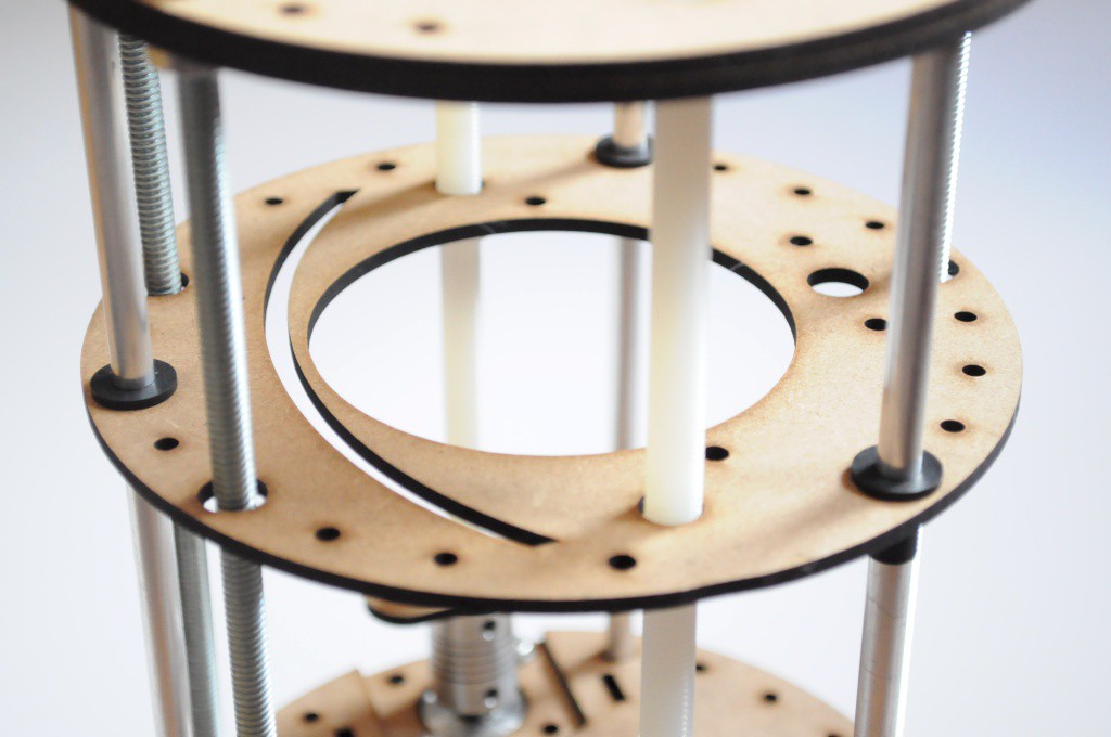
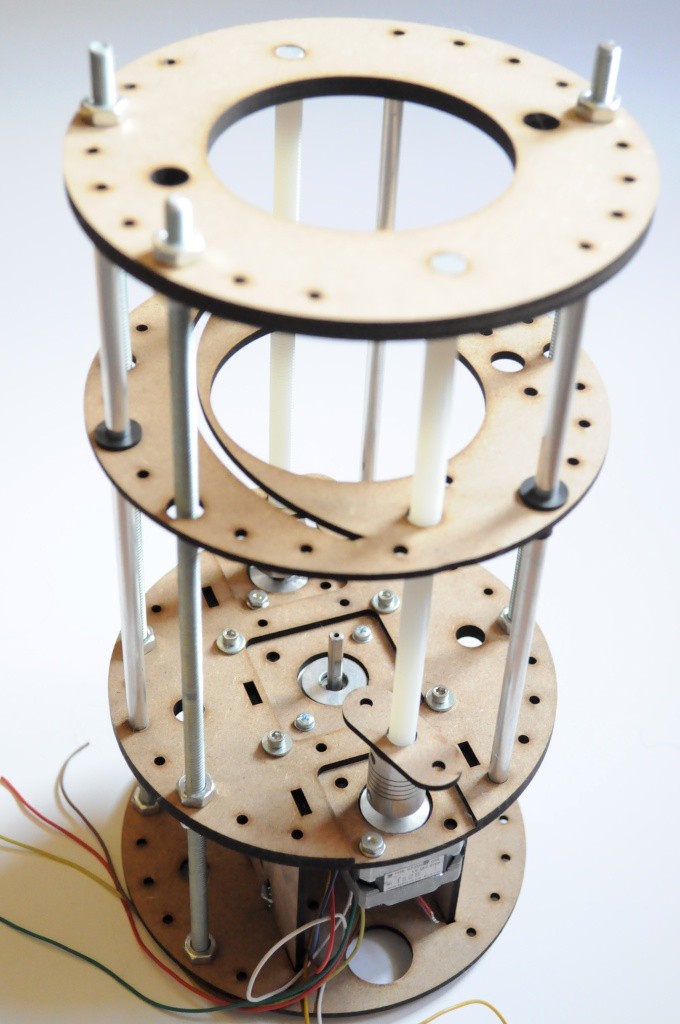
The source and detectors would be mounted on a moving Z-axis (shown above), that translates them up and down to capture different slices of the sample. While here I've included two stepper motors on nylon lead screws for this purpose, in practice this doesn't appear to provide enough support to prevent the Z stage from walking, especially with an unbalanced load — and so this will likely change to three lead screws in the next revision. The drive motors are currently NEMA14 steppers, with a NEMA17 footprint for the sample cylinder support and rotation.

So far a great first set of experiments and sketches, and it'll be interesting to better characterize the detector design, make improvements and revisions, and see how it all ultimately affects acquisition time.
Thanks for reading!
Discussions
Become a Hackaday.io Member
Create an account to leave a comment. Already have an account? Log In.
The schematic you upload in this log isn't large enough to read, any chance you can re-upload? Also, filling in the components list on your project would be very helpful. Thanks!
Are you sure? yes | no
I've re-uploaded a much higher resolution version that's much easier to read. There's also a link to a PDF of the schematic in the github repository above the image (in the text), but it's very easy to miss. I had originally tried to convince the editor to let the user click on the low-resolution schematic preview image to open the PDF, without success. :)
Are you sure? yes | no
Looks great, thanks for doing this!
Are you sure? yes | no