 peter jansen
A few years ago, while sitting in on a grad class in computational sensing, I (a Canadian) had my first real experience with the American healthcare system, and proclaimed whilst in (billing-related) shock that one day I would create a CT scanner for less than the billed cost of one scan. While I've had to scale back a bit over my original ambitions -- it's much smaller, and much slower, given my aversion to radioactive things -- in the past week I've felt as though it's really starting to take shape, and that a few months of planning and design revision are starting to come together.
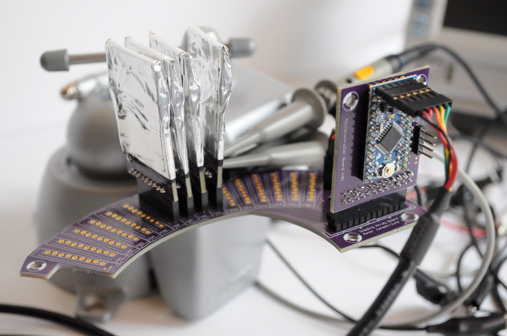
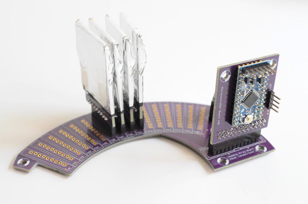
I had the chance to put together four of the modular radiation sensors, place them on the array board, populate the tiny Arduino control board -- and it all came together great. I wrote some very basic firmware that listens for pin-change interrupts, checks which pins have changed, and adds counts for the respective detector. It seems to be working wonderfully.
Like the Radiation Watch Type 5 detector in the Arducorder Mini, I added in a pulse width histogram into the driver for this imaging array, to see if it's capable of doing very crude spectroscopy. Unfortunately while pulse height is correlated with energy, pulse width with this detector is nearly always 10-20uSec, and not terribly useful for energy level discrimination. That being said, the digipot on the comparator allows one to dynamically set the detection threshold, so it's likely still possible to do energy level discrimination, but at the expense of multiple exposures. I'm looking forward to experimenting with this.
There is a bit of variance in the noise level of the detectors, and the digipots do clearly have to be set to slightly different values (a few millivolts apart) to see the same signal-to-noise characteristics on each detector. This is good to know, and really justifies having added the ability to individually set the comparator thresholds on each detector using the MCP23017 I/O expander.
I decided to make a major mechanical change, and increase the sample container size from 2 inches in diameter to 3 inches. I had originally planned to use a 3 inch container with a scan volume the size of a pop can, but lowered it both to (1) increase the signal-to-noise ratio, and (2) keep the total build size of the machine to within 6 inches in diameter.
While I had convinced myself that there'd be plenty of interesting things to scan that were less than 2 inches in diameter (like the bags of tiny peppers in the grocery store), after building the tiny 4-detector array, I simply couldn't find many things that would fit for a quick test -- everything was just slightly too big. Science is about trying not to fool yourself, when you're the easiest one to fool. I had fooled myself into thinking that the smaller diameter would work for the benefits in SNR, but when confronted with real test cases, it just isn't practical. This is a big of an expensive mistake given that it means I have to redesign the imaging array for a larger sample container size, but it's much better to make the change now and have a much more useful instrument.
Limiting the machine size to 6 inches in diameter also isn't practical for a 3 inch sample container, though I have had trouble sourcing larger 8 inch PVC tubes to use as an easy enclosure. David Forbes of Nixie Watch fame happened to know an online store that stocks a variety of PVC pipe sizes with very reasonable shipping for enormous heavy tubes, with an 8-inch diameter by 14-inch height thin-walled tube costing only about $20, shipped -- so this solved a major issue, and the size of the machine can now easily increase.
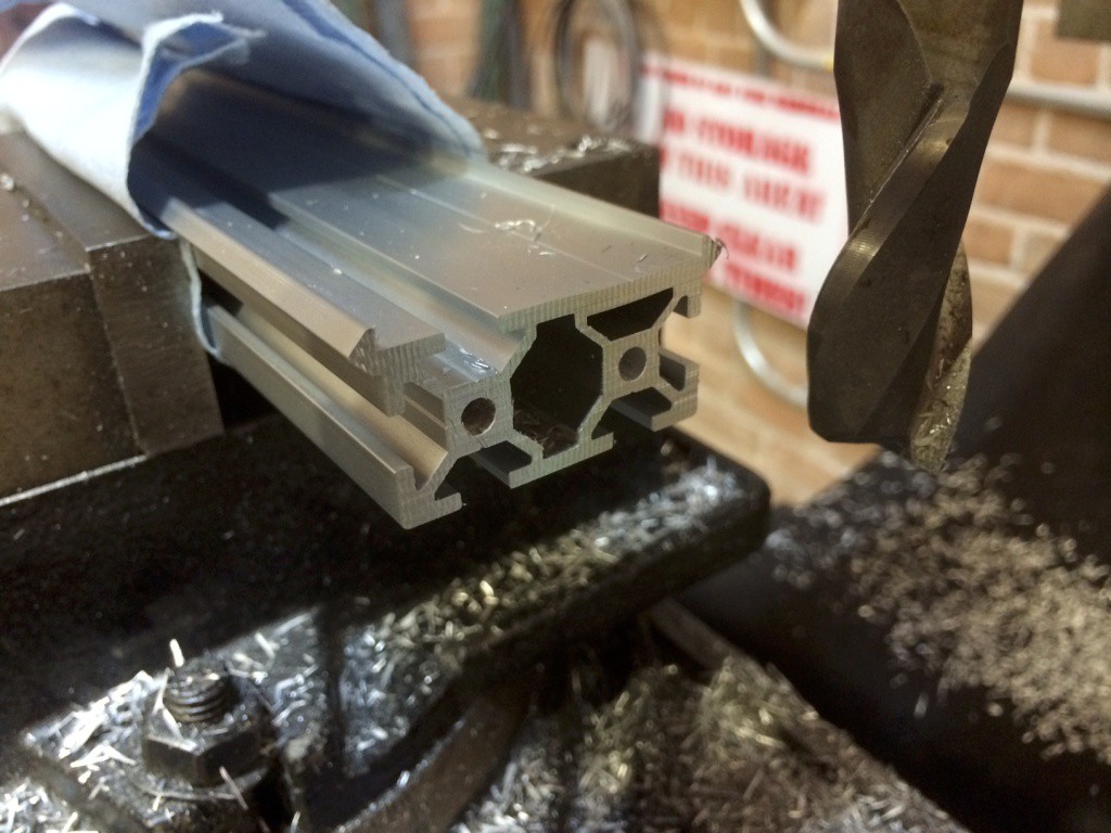
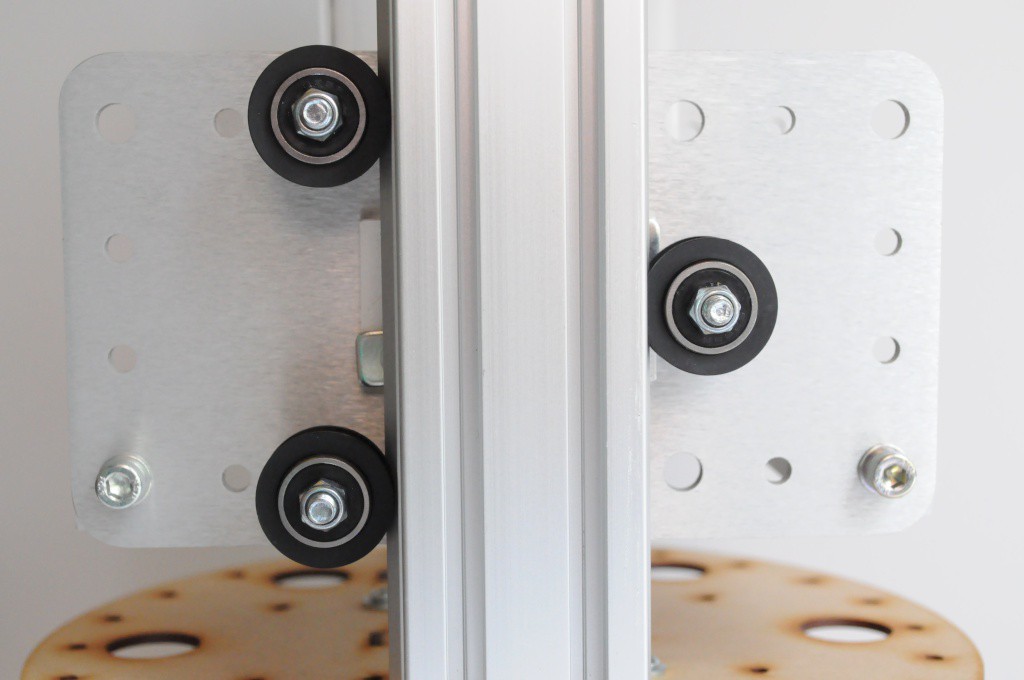
With an increase in size from 6 inches to 8 inches, this allows just enough room for more conventional linear motion systems, like the Makerslide v-wheel based aluminum extrusion. This is very easy to get ahold of through Inventables, and much more rigid than my laser cut system. Here I've cut down a large piece into two 24cm sections, and milled the faces to be completely flat after the cut.
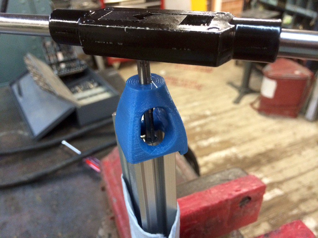
The Makerslide attaches to the frame on edge through two M5-tapped holes at either end of the extrusion. This 3D-printable tapping jig on Thingiverse is absolutely essential for this -- a few years ago I tried tapping Makerslide without a jig, and the result was horrible. "Cut a full turn, then back off half a turn to let the material work it's way out. Keep repeating this until your tap is too dirty or the hole is deep enough. Don't forget to use tapping fluid!" -- thanks Dad.
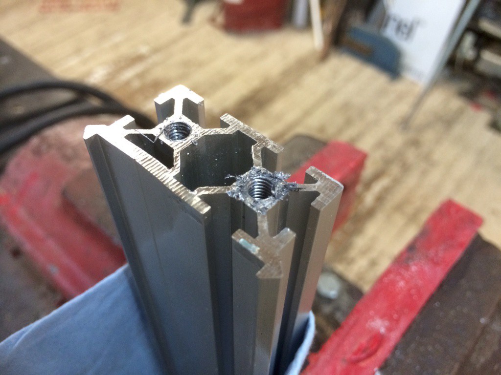
Following the above advice can really lead to some very successfully tapped holes.
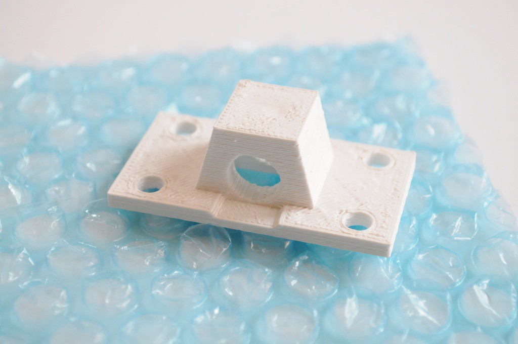
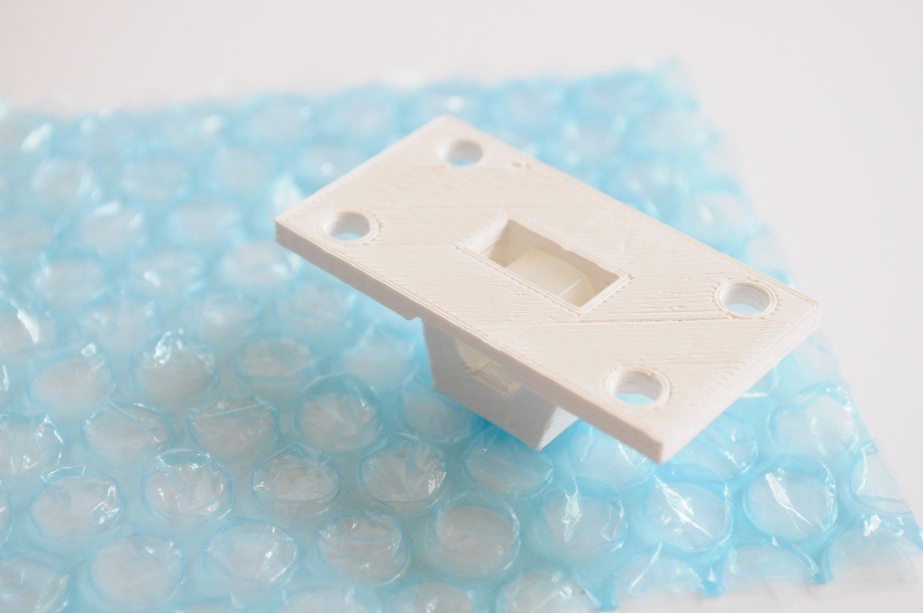
While Makerslide provides a very solid slide and carriage, we still need a way to transfer linear motion from a stepper motor to that carriage. I prefer using lead screws for this application rather than belts since the load can rest on the leadscrew, even when the stepper motor isn't powered. Here I've put together a small printable nut holder that low-profile enough to live between the Makerslide and the carriage, and attach with normal M5 extrusion bolts and t-slot nuts.
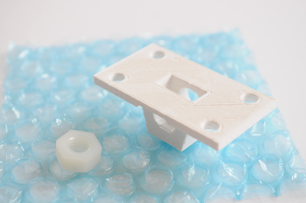
A nylon M8 nut very snugly fits into the back of the nut holder.
Allowing an M8 threaded nylon rod to be threaded through, and used to transfer linear motion.
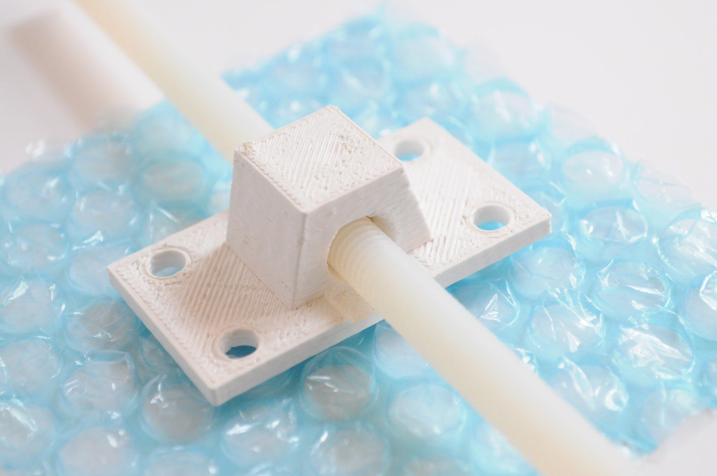
While the nylon might seem like an unusual material to use for transferring linear motion, it tends to have a small amount of mechanical play that allows it to self-align when coupled with a rigid linear rail like the Makerslide. I've used traditional steel threaded rod before, but I've found that the small diameter rod tends to bend very easily (even while shipping), and it makes alignment and binding a constant issue. The nylon solves this issue, has a very low friction and wear without lubrication, and is very inexpensive.
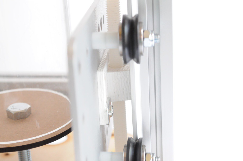
Here the printed nut holder can be seen sandwiched between the carriage that it's bolted to, and the Makerslide rail.
The holder is designed to mate with the footprint on a standard wheel carriage plate, to make the linear motion system as rigid and off-the-shelf as possible.
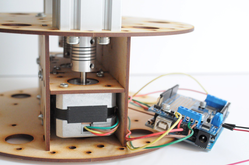
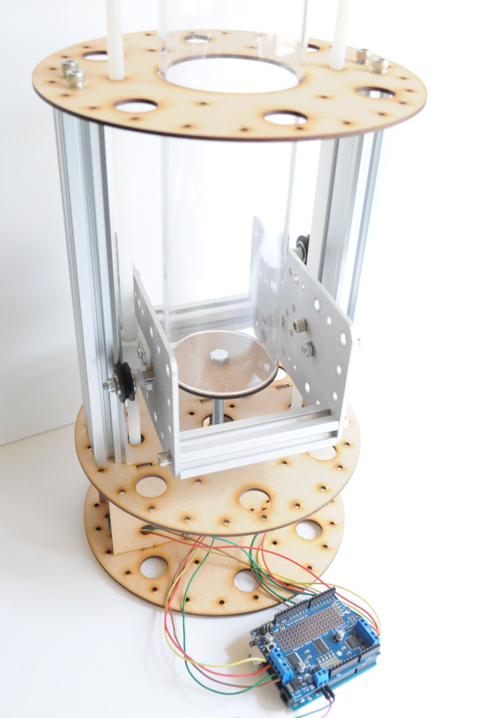
At the bottom, the four NEMA14 motors have been replaced with three NEMA17 motors from Adafruit -- two for the two Makeslide rails, and one to rotate the table. Since the two motors for the linear rail system move in unison, all three motors can be connected to a single Arduino motor shield. 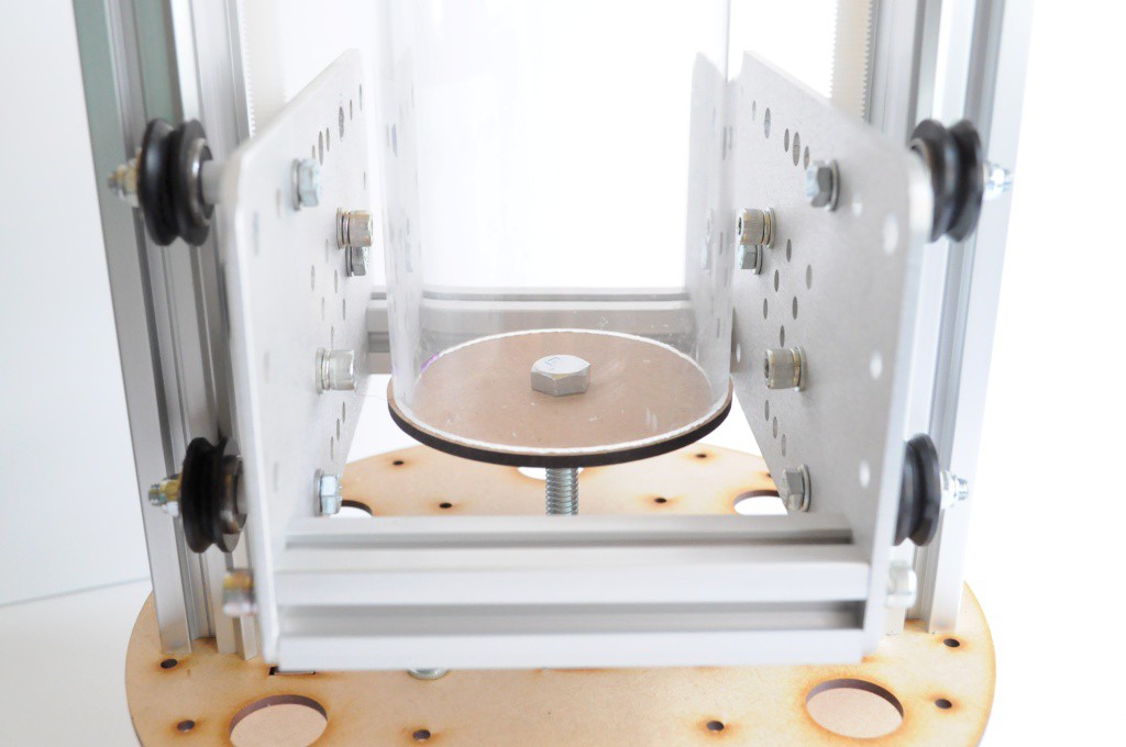
Two 10cm pieces of Misumi aluminum extrusion bridge the gap between the carriages, and provide a solid surface to mount both the detector array (on one side) and the Barium-133 radioisotope source (on the other). The table mock-up is currently just a 3 inch disk, but eventually will need a proper mechanism that couples to the sample container, as well as a bearing to restrict the motion of any off-balance samples.

And it works! With a very smooth motion, on both the linear and rotational axes.
Thanks for reading!
Discussions
Become a Hackaday.io Member
Create an account to leave a comment. Already have an account? Log In.
Really love this project!
I have a question: Have you tested if the stepper motors will introduce EMI on the detectors? This all off course depends on the chosen drives/motors. But a quick test now, can save a lot of troubleshooting hours later.
The reason I ask this because we once had a customer at our company who also did very accurate measuring. We were required to completely turn off the motors for every measurement. The holding torque (currents) created enough noise to be visible on the measurements. We only did the motion part so I do not known about the actual measuring.
Are you sure? yes | no
This is a very good question! One of the reasons that I've used a lead screw instead of a belt is to be able to turn the motors off in between measurements, both to reduce any potential for interference, and reduce the power consumption.
I'm not entirely sure yet whether the Adafruit Motor Shield that I'm using can disable the steppers -- I had originally planned on making a small shield with Pololu controllers for this purpose, but I'm really hoping to keep the mechanical platform entirely off the shelf (if possible) to make it easy for folks to reproduce.
Thanks for your comment!
Are you sure? yes | no
np
When you turn off the motors and back on again their position can change. Especially when using micro stepping. The drive will not remember the micro stepping it was using. These small errors can really add up over hours.
So when you decide to turn off the motors for each measurement also think off something clever to solve this problem ;) Homing every x moves or absolute measuring of the position.
Are you sure? yes | no
That's really interesting, and not something I had considered. The lead screw is such a fine pitch that a full turn results in only about a millimeter of vertical motion, so it's using full step mode (instead of microstepping), and being off by a few steps should equate to hundredths of a millimeter. With a pixel size of about 3mm, it sounds like in the worst case it could be off by about 1mm over the entire vertical travel. That probably wouldn't make too much difference in the images, but it's definitely worth being aware about. Encoders would be a lot of trouble just for ~0.05mm image registration issues, but there should be endstops to use for homing each translation (or every N translations) if it comes to it... Thanks!
Are you sure? yes | no
If you design your own board, you may be able to run a circuit that "Locks" your steppers into their given phase, but does not generate as much noise as a driver. The only problem is current limiting without using noisy PWM (you might try a dedicated regulator with current limiting).
The rotational axis would be easy to home each cycle, you could simply have a hall effect or inductive sensor (like 3D printer bed level) (or even a mechanical switch) that tripped once per rotation, and use that to calibrate. That way you would not have to home all the way back to the ground and back up each time.
Are you sure? yes | no