 peter jansen
One step back then two steps forward, I've captured the first one dimensional data from the detector array!
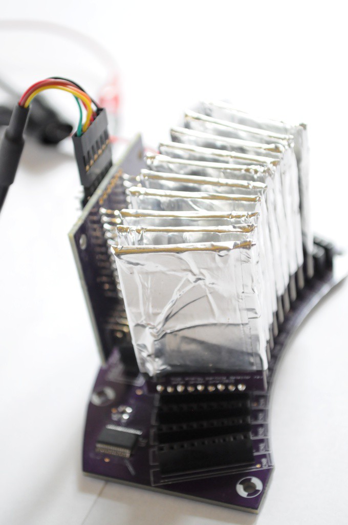
The new imaging array is now populated with 10 of the 16 total detectors, and this is very exciting. I tend to try and keep things positive, but sometimes things go well, and sometimes things happen that slow things down. It's always important to make your mistakes cheaply whenever possible, and this week several things happened -- and while they were not terribly expensive issues, they were preventable.
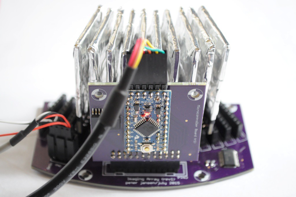
An incorrectly labelled footprint: The Arduino Pro Mini has exactly enough pins to monitor the output of the 16 detectors, and communicate to each detector's digipot (which calibrates that detector's sensitivity) using SPI. Because there are 16 detectors and 16 chip select (CS) lines for the digipots, the Imaging Array board also contains a Microchip MCP23017 16-bit I/O expander, connected to the Arduino Pro Mini using I2C. Exactly enough pins.
Unfortunately as it turns out, two pins on the Arduino Pro Mini (A6/A7) are not available to use as digital pins, and I discovered this only when two detector channels were silent. I revised the microcontroller board to include it's own I2C I/O expander for the extra two pins, but it turns out the open source footprint I used was incorrect, and when I powered the board the I/O expander caught fire. It was an easy mistake for whoever made the footprint to make -- and I try to make my own footprints to ensure that they're correct, but I was pressed for time. A few days later the part was swapped, and the board running again. This wasn't a big deal, but it did cost a few days of waiting for parts to arrive.
Bridging the 5V and 40V lines.
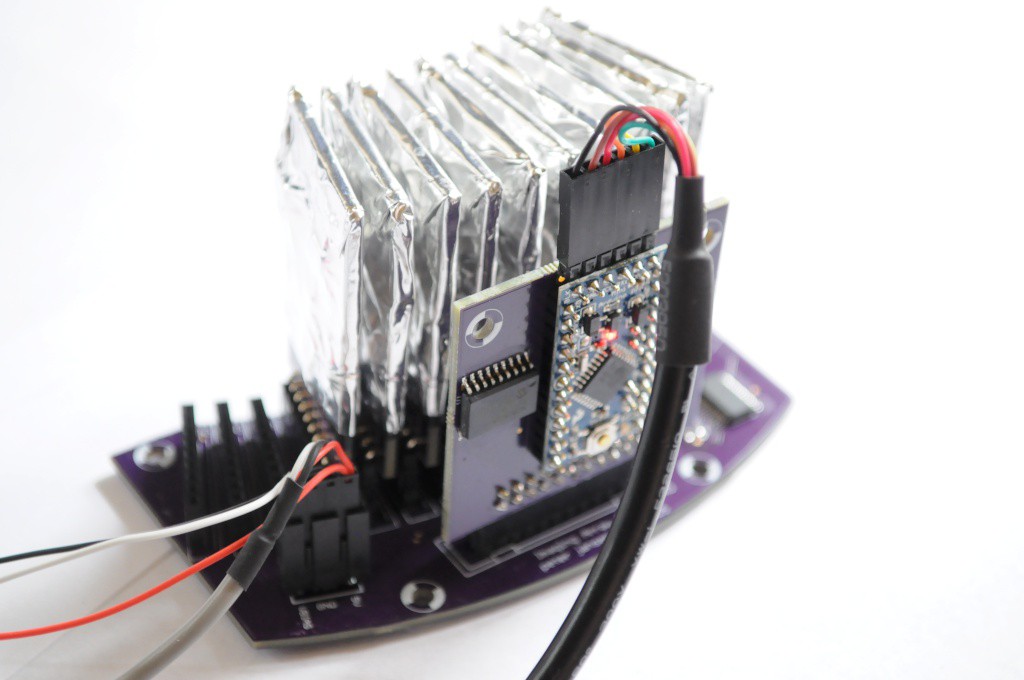
To make up the few days I lost waiting for parts to come in for the microcontroller board, I worked a little too quickly. The Imaging Array board has a polarized 4-pin power connector that connects to a power cable, and right now this cable is connected to two different supplies through alligator clips -- 5V for the analog bits on the detectors, and 40V for the photodiode bias. I usually place a little electrical tape over these alligator clips to prevent them from bridging, and while this tape was present, in my haste I didn't replace it, and kept on the older tape from a few days ago.
Unfortunately over about an hour of firmware debugging and detector testing the glue on the tape slowly let go and the tape on two alligator clips opened up, bridging the 5V and 40V lines. Nearly everything connected went up -- two detector modules, the freshly-soldered microcontroller board, and even the USB hub didn't enjoy 40V being placed through it. It's been years since I've blown anything up, and I blew up two things only a few days apart!
This was more expensive in time than anything else -- it takes about 2 hours to completely assemble and test a detector, and an hour for the microcontroller board. ("That's why I fuse everything!" -- my dad, an industrial engineer. Thanks dad -- I had planned on including a fuse on the power supply, but clearly I should have placed one on the imaging board itself!).
The laser cutter stopped working
Unfortunately our beautiful laser cutter at Xerocraft went through another tube a week ago, and at a very inconvenient time -- just as I was about to teach a laser cutter class. It'll likely be another week until a replacement is here, and I'm eagerly awaiting its arrival so that I can fabricate the mount that secures both the imaging array and Ba133 radioisotope source to the Z stage.
Assembling additional detectors
With only 6 detectors post explosions, and no laser cutter to build a mounting bracket, it was time to assemble more detectors. I have found that when hand assembling them, doing so in batches of 4 tends to maximize throughput -- it takes about 3 hours to go from 4 bare boards to pasted boards to populated boards to toaster-oven reflowed boards. After cooling down, it takes about another hour or so to wrap the boards in electrical tape, apply the aluminum shield tape, solder on the ground wires, and finally populate the 9-pin right angle connector on the bottom that allows each detector to plug into the imaging array.
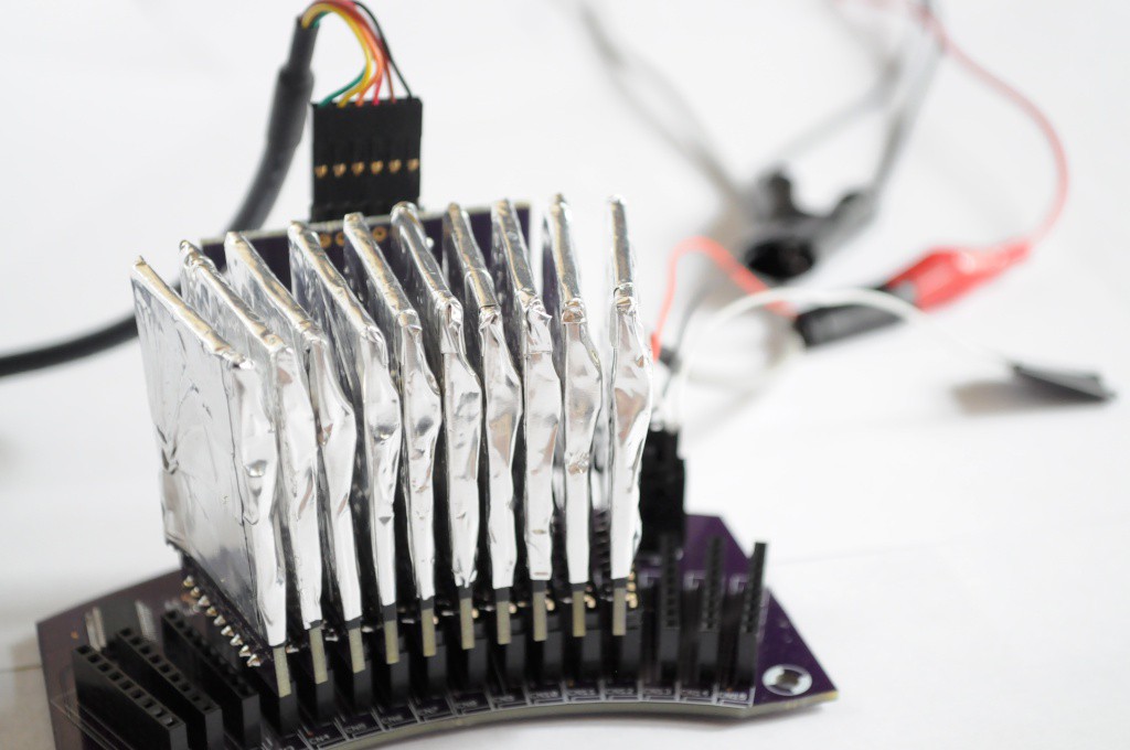
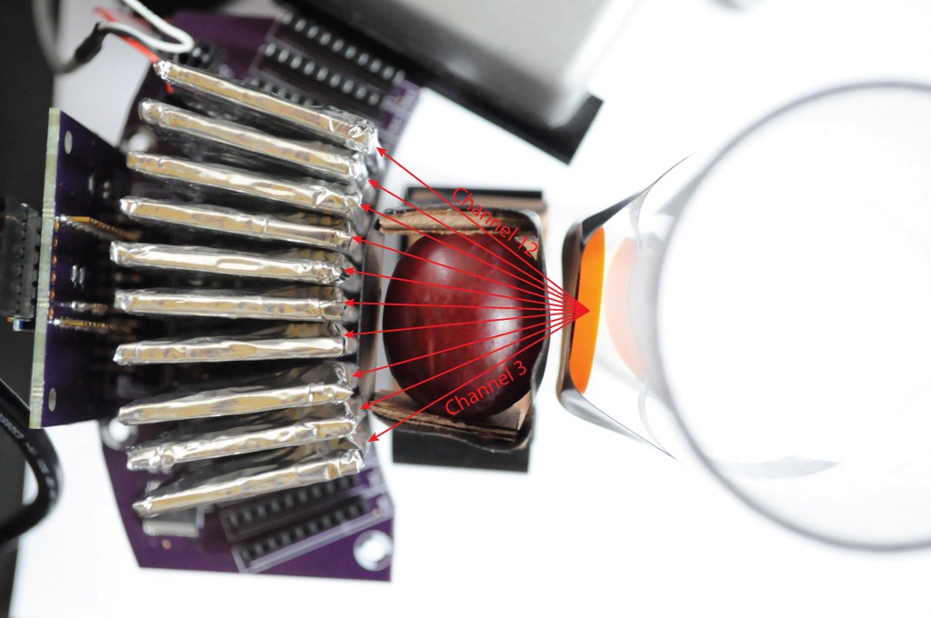
With a total of 10 detectors currently populated, I snapped some pictures of the imaging array before capturing the first data. The picture above is one of my favorite from this project so far -- the crisp contrast of purples and whites/greys along with the coloured cables is really aesthetically pleasing.
One of the most wild things to me is that this is a camera. Taking a step back, It's really incredible to think that high energy particles like x-rays and gamma rays just sail right through the aluminum tape to a highly charged detector that amplifies the signal of those single photons by about a million times so that they can be individually counted, and does this with an efficiency of about 1% for the Barium 133 radioisotope photons. Of course very similar modules have been inside CT scanners for about 30 years, and the ones in use today are incredible and far more sophisticated than this -- but it's still very exciting to me, and I'm not aware of anyone else having tried to develop their own highly-efficient imaging array for very low intensity sources, or such an inexpensive array for pedagogical purposes.
An Image of the Grape
I've been itching to collect real data off the array for a while, and with the laser cutter out of commission until the new tube arrives, actually mounting the array and source in the detector will have to wait for a week or two.
To get around this, I taped the Ba133 source to a plastic tube at the same height as the detectors, and taped a delicious grape in a mount between the source and imaging array. I chose the grape because it's mostly water, which is highly absorptive to high energy particles, and so it should provide a good amount of contrast.
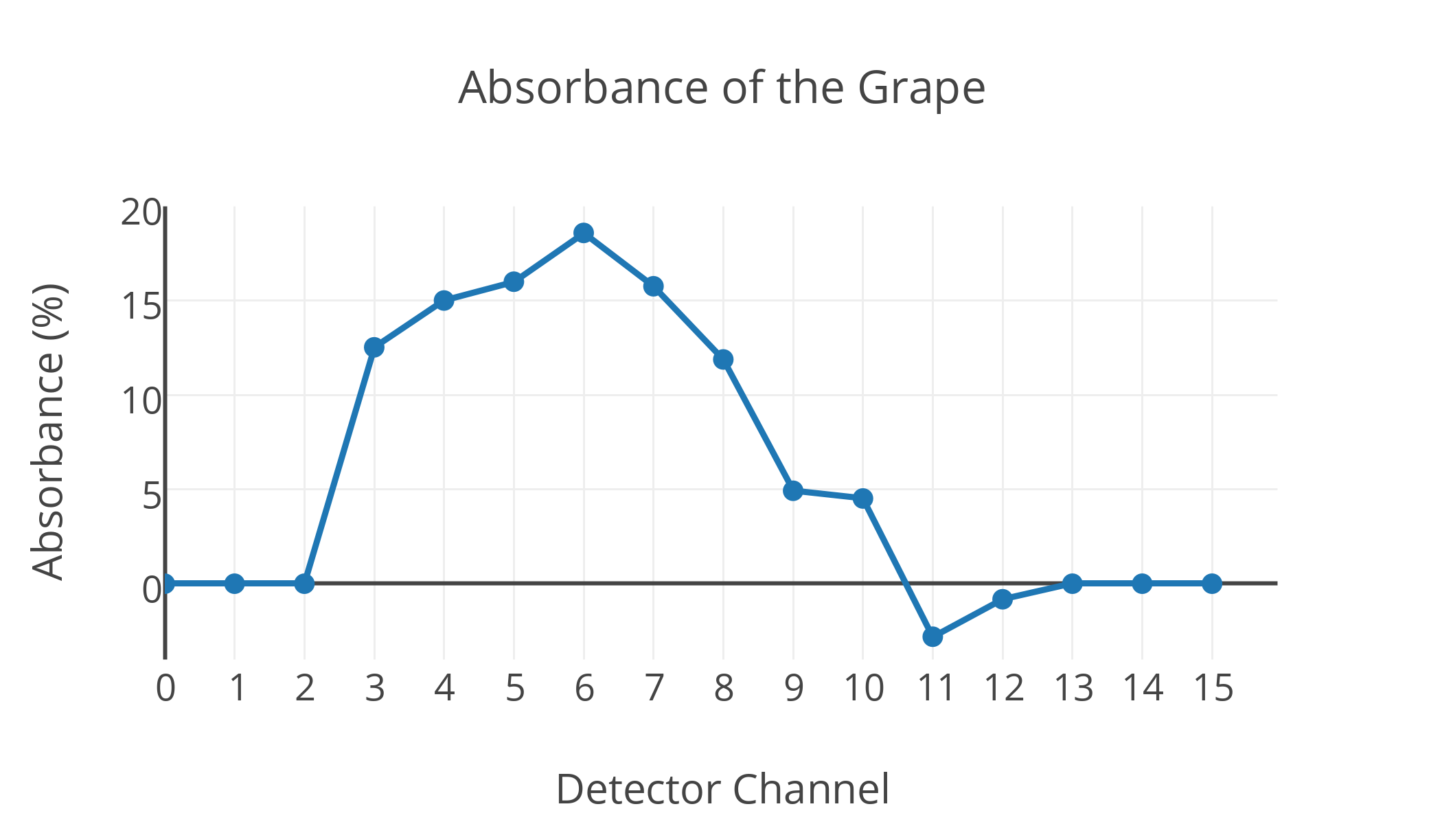
Above is a graph of the x-ray absorbance measured on each detector channel from the grape, with a sample time of a few minutes. The absorbance reflects the difference between sampling for a few minutes (without the grape) to get a baseline reading for each channel, and then sampling with the grape to measure the relative absorbance.
Lining up the absorbance values for each detector channel with the picture above, we can see there is clearly more absorbance on the channels that have to go through more grape. This peaks with nearly 20% absorbance at channel 6, which goes straight through the center of the grape, and is much smaller for channels 9-12, which just graze the edge and thus go through comparatively less grape. Here the variance is limited by the shot noise of the extremely low intensity radioisotope source, and decreases with increased integration time. This is why some channels with very low absorbance (like channel 11) can appear to have a negative absorbance relative to the baseline -- with this integration time there's likely to be a variance of about 4%, so an absorbance of -2% is well within the error.
Very exciting to see some first data -- with some luck I'll be able to populate the remaining detector channels shortly, mount the array to the tomographic platform, and begin to take some 2D images and tomographic slices in the next few weeks!
Thanks for reading!
Discussions
Become a Hackaday.io Member
Create an account to leave a comment. Already have an account? Log In.
First of all, it's a great project and very fun! I have a couple of questions:
Since you are counting events, can you provide a relation of the negative positive and positive positive events, or am I misunderstanding this?
And, where manufacture your designs?
Are you sure? yes | no
congratulations on the data!
Commiserations on the blue smoke.
Hope to see more progress soo
Are you sure? yes | no
Are all detectors individually tuned close to the noise floor?
Are you sure? yes | no
This is a very good question. I have chosen high tolerance versions of all the passives to ensure that each detector is as close to the others across a wide temperature range, so that ideally one would be able to choose one digipot value that would work across all detectors. In practice it looks like there is some variation between detectors, and the noise floor ends up being somewhere around (currently) 170 +/- 3 (out of 255) on the digipot.
Are you sure? yes | no
High tolerance as in high precision? Do you have a rough idea on the amplitude of the noise floor? Is it definitely related to the shot noise?
Are you sure? yes | no
My apologies for not getting back to your github comment earlier (the lab is /very/ busy) -- your comment is very interesting, and I'm very happy that others are interested in the noise-related questions. I'd like to use the question as a motivation to design a SPICE model to figure out exactly where the noise issues are, and (ideally) bring the noise floor down to below the ~33keV emissions of Ba133, but most of the approaches I've seen suggest a noise floor lower than 40-60keV is extremely challenging to get to.
To your questions -- the parts on this detector are both high precision, and have a wide temperature tolerance to keep that precision over a large-ish temperature range, incase it warms up while in the enclosure (though this will still likely require characterization and calibration, so I've included thermistors on each detector).
The noise model is slightly more complicated, since there are two levels of signal, each having their own noise. At the analog signal/amplifier level, the primary sources of noise are likely to be the very high valued (47M) resistor for the extremely large gain stage, the capacitance of the photodiode (which was selected to be very low), and the thermal noise of the amplifier. The noise floor tends to be around 40 to 70mV, depending on the gain set with the initial capacitor (4.7nF vs 2.2nF), but the overall level of signal appears the same -- the amplitudes are just larger -- suggesting other aspects (like the resistor and thermal noise of the amplifier) are dominating the noise.
Once you have put this signal through the comparator on the detector and how have a series of counts representing the number of high-energy photons hitting the detector for a given time (say 70 counts per minute), the dominant noise in this estimate of emissions-per-unit-time is shot noise. This is a matter of physics, and not much can be done about it other than increasing the intensity of the source (or increasing integration time) -- it just so happens mother nature had 70 barium isotopes decaying on that side of the sample one minute, and 90 the next minute. Given the source intensity constraints (the maximum intensity of source purchasable without a license), there's not much that can be done about this.
The caveat to that is the first issue -- the signal to noise radio of the analog portions of the detector itself. Backing out the expected number of counts (from all emissions) versus the number measured, it looks like the detector is currently only about 1% efficient. In the simplest case, boosting this to 100% efficiency would decrease the acquisition time by sqrt(100) or 10 times. Of course you likely can't make a solid state detector that efficient (some of the photons just won't interact with the photodiode), but ~30keV photons are much more strongly interacting than the ~80keV ones that are likely being detected, so it's possible it might be able to be brought up from 1% efficient to 10-30% efficient (specifically for Ba133). That'd still be a huge gain, and (assuming lots of things, like the same contrast, etc), decrease the measurement uncertainty, and decrease the measurement time substantially.
I think modeling the current detector front end in SPICE to understand (precisely) the noise constraints would be incredibly beneficial, and help determine whether a next-generation detector is feasible, and where to target.
There's also the possibility of using a scintillator, though I have tried this very briefly (and honestly I'm not an expert on scintillators), and it did not yield very good performance, and was expensive. I think large chunks of scintillators with cooled photomultiplier tubes or avalanche photodiodes are able to do single photon counting, but this would be enormous and very expensive compared to the tiny detector here.
Of course if radiation exposure and health/regulatory concerns wasn't an issue and you were looking at non-biological samples, you could likely use the current setup with a much more intense source and have very good exposures with short integration times, as the 1% efficiency wouldn't be much of an issue.
Working directly at the limits of the noise floor isn't necessarily all that easy sometimes, but it's certainly a lot of fun. ;)
Are you sure? yes | no
Good read, indeed!
Are you sure? yes | no
This remains one of the most interesting tool-projects on HaD by far, keep up the great work
Are you sure? yes | no
thanks!
Are you sure? yes | no
thanks for writing this update, it was a good read! Sounds like a tough week, I once ran into this "A6/A7 is no digital pin" thing, too. Good luck to you and your project!
Are you sure? yes | no
Thanks! I'm really trying to make this thing easy for other folks to put together, and the pro mini seemed like a very easy-to-solder and inexpensive choice. There may be 18 pins worth of I/O expanders connected to it, but it seems to work well. :)
Are you sure? yes | no