Close
0%
0%

Survey Rover

A Survey Rover is survey tool for measuring point-to-point distance using a remotely operated rover.

Similar projects worth following
What is a Survey Rover? A Survey Rover is survey tool for measuring point-to-point distance using a remotely operated rover.

This Survey Rover project is perfect for researchers, educators and hobbyists alike. Using 2.4" gen4 HMI distance module mounted on a hand-held RF controller this surveyor has the ability to store the measured distance.

For this project you will need the following:
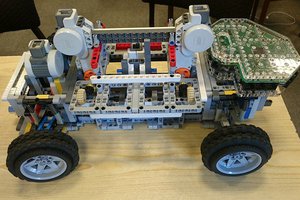
HARDWARE COMPONENTS

  • gen4-uLCD-24DT
  • gen4-PA and FFC Cable
  • 2 x Arduino Uno
  • 1 x Motor shield
  • 2 x nRF905 transceiver module
  • 2 x DC motors
  • 3 x Wheels
  • 1 x Car chassis
  • Magnetic hall effect sensor module
  • Small magnets
  • Joystick Module
  • 5 V power supply
  • Assorted nuts and bolts
  • uSD Card
  • uUSB Cable
  • Jumper Wires

SOFTWARE APP

For the implementation you can go to this link.

  • 1
    BUILD

    Transmitter Circuit

    Rover Circuit


  • 2
    Program
    • Extract the contents of the files.


    • Copy the nRF905 library file to the Arduino library location.
    • Open the project file for Rover using Arduino IDE. This contains the code for the Arduino Uno in the rover car.
    • You can check and modify the transceiver address of the rover’s radio module.


    • You can check and modify the codes for the rover movement routines here


    • Open the project file Controller using Arduino IDE. This contains the codes for the Arduino Uno in the handheld controller.
    • You can also check and modify the codes for the data receiving and timeout on the controller side.


    • You can also check and modify the codes for assembling the data to be sent to the display here.


    • You can check and modify the codes for the joystick commands here.


    • Open the Controller Display file using Workshop 4. This project uses the Visi Environment. This contains the code for the display on the handheld controller.
    • You can modify the properties of each widget.
    • You can check and modify codes for receiving serial commands from the Arduino controller and the odometer routine here.


    • You can check and modify the speedometer function shown in the snippet below.


    • You can check and modify the codes for showing the data results on the display.


    • You can check and modify the codes for converting encoder data to speed and distance measurements in English and metric units.


  • 3
    Upload and Compile
    • Click on the “Compile” button.

    Note: This step could be skipped. However, compiling is essential for debugging purposes.

    • Connect the display to the PC. Make sure that you are connected to the right port. Red Button indicates that the device is not connected, Blue Button indicates that the device is connected to the right port.
    • Go back to “Home” tab. This time, click on the “Comp’nLoad” button.

    •  Workshop 4 IDE will prompt you to select a drive to copy the image files to a uSD Card. After selecting the correct drive, click OK.

    • The module will prompt you to insert the uSD card. 
    • Unmount the uSD Card properly from the PC and insert it to the uSD Card slot of the display module.

View all 3 instructions

Enjoy this project?

Share

Discussions

lindahd wrote 07/30/2022 at 11:06 point

I have read totally about this project. Your detailed explanation helped the team of survey portal https://www.homedepotcomsurveyss.com/

  Are you sure? yes | no

rhatem.thabet wrote 06/21/2021 at 18:04 point

I like your program. Can I modify it for my survey page? You can see my page detail here https://erasurvey.org/mypricerite-experience/

  Are you sure? yes | no

Similar Projects

Does this project spark your interest?

Become a member to follow this project and never miss any updates